CBSE Sample Papers for Class 12 Physics Set-1
Class 12thCBSE Sample Papers for Class 12 Physics Set-1
CBSE Sample Papers for Class 12 Physics Set-1
Time : 3 hrs
Max. Marks : 70
Instructions:
1. There are 33 questions in all. All questions are
compulsory.
2. This question paper has five sections : Section A, Section B,
Section C, Section D and Section E.
3. All the sections are compulsory.
4.
Section A contains sixteen questions, twelve MCQ and four Assertion Reasoning
based of 1 mark each, Section B contains five questions of two marks each,
Section C contains seven questions of three marks each, Section D contains two
case study based questions of four marks each and Section E contains three long
answer questions of five marks each.
5. There is no overall choice. However,
an internal choice has been provided in one question in Section B, one question
in Section C, one question in each CBQ in Section D and all three questions in
Section E. You have to attempt only one of the choices in such questions.
6.
Use of calculators is not allowed.
7. You may use the following values of
physical constants where ever necessary.
(i) c = 3 × 10⁸ m/s
(ii) me = 9.1 × 10⁻³¹ kg
(iii) e = 1.6 ×
10-19 C
(iv) µ0 = 4π × 10-7
TmA-1
(v) h = 6.63 × 10⁻³⁴ Js
(vi) ε0 =
8.854 × 10-112 C2N-1m-2
(vii)
Avogadro’s number = 6.023 × 10²³ per gram mole
SECTION A
Question 1.
Which of the following is not the property of an equipotential
surface?
(a) They do not cross each other.
(b) The work done in carrying a
charge from one point to another on an equipotential surface is zero.
(c) For
a uniform electric field, they are concentric spheres.
(d) They can be
imaginary spheres.
Answer:
(c) For a uniform electric field, they are
concentric spheres.
For a uniform electric field, the equipotential surfaces are the plane surfaces and the gap between two consecutive equipotential surfaces will be same.
Question 2.
An electric dipole placed in an electric field of intensity 2
× 105 N/C at an angle of 30° experiences a torque equal to 4 N-m. The
charge on the dipole of dipole length 2 cm is
(a) 7 µC
(b) 8 mC
(c) 2
mC
(d) 5 mC
Answer:
(c) 2 mC
Given, E =2 × 10⁵ N/C, θ = 30°, τ = 4 N-m,
2a = 2 cm =2 ×
10-2 m
The torque on an electric dipole in uniform electric
field,
τ = q(2a) – E sinθ
4 = q × 2 × 10-2 × 2 × 105
× sin 30°
q = 2 × 10⁻³C = 2 mC
Question 3.
A metallic plate exposed to white light emits electrons. For
which of the following colours of light, the stopping potential will be
maximum?
(a) Blue
(b) Yellow
(c) Red
(d) Violet
Answer:
(d)
Violet
Einstein’s photoelectric equation,
eV0 = h(ν – ν0) =
\(\frac{h c}{\lambda}-\phi_0\)
Stopping potential, V0 ∝
\(\frac{1}{\lambda}\)
∴ The colour with minimum wavelength, i.e. violet
colour has maximum stopping potential.
Question 4.
When α-particles are. sent through a thin gold foil, most of
them go straight through the foil, because
(a) a-particles are positively
charged
(b) the mass of an α-particle is more than the mass of an
electron
(c) most of the part of an atom is empty space
(d) α-particles
move with high velocity
Answer:
(c) most of the part of an atom is empty
space
When a-particles are sent through a thin gold foil, most of them go straight without deviation, because most of the part of an atom is empty space.
Question 5.
An electron is moving along positive x-axis in a magnetic
field which is parallel to the positive Y-axis. In what direction, will the
magnetic force be acting on the electron?
(a) Along – X-axis
(b) Along –
Z-axis
(c) Along + Z-axis
(d) Along – Y-axis
Answer:
(c) Along +
Z-axis
The force on a moving charge in uniform magnetic field,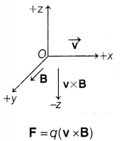
As, electron has negative charge, Fe = – e(v ×
B)
∴ The direction of force on electron is opposite to the direction of v × B
i.e. in +z-direction.
Question 6.
The relative permeability of a substance X is slightly less
than unity and that of substance Y is slightly more than unity, then
(a) X is
paramagnetic and Y is ferromagnetic
(b) X is diamagnetic and Y is
ferromagnetic
(c) X and Y both are paramagnetic
(d) X is diamagnetic and Y
is paramagnetic
Answer:
(d) X is diamagnetic and Y is paramagnetic
The relative permeability of a substance, μr = 1 +χ
For
diamagnetic substance, χ = -ve
μr < 1
For paramagnetic
substance, χ = + ve
μr > 1
Hence, X is diamagnetic and Y is
paramagnetic substance.
Question 7.
An ammeter of resistance 0.81 Ω reads up to 1 A. The value of
the required shunt to increase the range to 10 A is
(a) 0.9 Ω
(b) 0.09
Ω
(c) 0.03 Ω
(d) 0.3 Ω
Answer:
(b) 0.09 Ω
For an ammeter,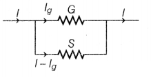
l = 10 A,G = 0.81 Ω, lg = 1A
∵ VG =
VS ⇒ lg . G = (l – lg).S
∴ S =
(\(\frac{1}{10-1}\)) × 0.81 = 0.090
Question 8.
An electron with angular momentum L moving around the nucleus
has a magnetic moment given by
(a) e L/2m
(b) e L/3m
(c) e L/4m
(d)
e L/m
Answer:
(a) e L/2m
The magnetic moment of electron moving around nucleus,
μ = iA =
\(\frac{e}{T}\) . πr² = (\(\frac{e}{\frac{2 \pi r}{v}}\)) . πr²
∴ μ =
\(\frac{evr}{2}\)
As, angular momentum of electron, L = mvr
⇒ vr =
\(\frac{L}{m}\)
From Eqs. (i) and (ii), we get
∴ μ = \(\frac{eL}{2m}\)
Question 9.
The large scale transmission of electrical energy over long
distances is done with the use of transformers. The voltage output of the
generators is stepped-up because of
(a) reduction of current
(b) reduction
of current and voltage both
(c) power loss is cut down
(d) (a) and (c)
both
Answer:
(d) (a) and (c) both
As power, P =V.I = constant
For a step-up transformer,
VOutput < Vinput ⇒ Iinput >
IOutput
Current is reduced and power loss is cut down.
Question 10.
The diagram below shows the electric field (E) and magnetic
field (B) at a certain time and location.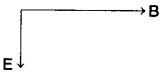
The direction of the propagation of the electromagnetic wave
is
(a) perpendicular to E and B and out of plane of the paper
(b)
perpendicular to E and B and into the plane of the paper
(c) parallel and in
the same direction as E
(d) parallel and in the same direction as B
Answer:
(a) perpendicular to E and B and out of plane of the paper
As, the direction of propagation of electromagnetic wave is in the direction of E × B, Flence, the direction of EM wave will be perpendicular to E and B and out of plane of paper.
Question 11.
In a coil of resistance 100 Ω, a current is induced by
changing the magnetic flux through it. The variation of current with time is as
shown in the figure. The magnitude of change in flux through coil is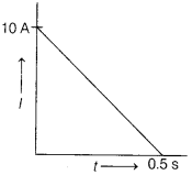
(a) 200 Wb
(b) 275 Wb
(c) 225 Wb
(d) 250 Wb
Answer:
(d) 250 Wb
Given, R = 100 Ω
According to Faraday’s law,
l = \(\frac{1}{R}
\frac{\Delta \phi}{\Delta t}\)
∆ϕ = (l∆t)×R
The magnitude of change in
flux through coil,
∆ϕ = (Area of l.t curve) × R
= \(\frac{1}{2}\) × 0.5 ×
10 × 100 = 250 Wb
Question 12.
The energy of an electron in nth orbit of hydrogen atom is
En = (-13.6/n2)eV. The negative sign of energy indicates
that
(a) electron is free to move
(b) electron is bound to the nucleus
(c) kinetic energy of electron is equal to potential energy of electron
(d)
atom is radiating energy
Answer:
(b) electron is bound to the nucleus
The energy of electron in nth orbit of Fl-atom,
En =
\(-\frac{13.6}{n^2}\) eV
Here, negative sign indicates that the electron is
bound to the nucleus.
For Questions 13 to 16 Two statements are given-one labelled Assertion (A)
and other labelled Reason (R). Select the correct answer to these questions from
the options as given below.
(a) Both Assertion and Reason are true and Reason
is the correct explanation of Assertion.
(b) Both Assertion and Reason are
true but Reason is not the correct explanation of Assertion.
(c) Assertion is
true but Reason is false.
(d) Both Assertion and Reason are false.
Question 13.
Assertion (A) For the radiation of a frequency greater than
the threshold frequency, photoelectric current is directly proportional to the
intensity of the radiation.
Reason (R) Greater the number of energy quanta
available, greater is the number of electrons absorbing the energy quanta and
greater is number of electrons coming out of the metal.
Answer:
(a) Both
Assertion and Reason are true and Reason is the correct explanation of
Assertion.
For the frequency of radiation, ν > ν0 photoelectric effect
takes place and the photocurrent is directly proportional to the intensity of
radiation.
i.e. Intensity ∝ Photocurrent
\(\frac{\text { Number of photon
}}{A \cdot t} \propto \frac{\text { Number of electron }}{t}\)
⇒ Number of
photons oc Number of electrons
Hence, greater the number of photons or
quanta, greater is the number of emitted electrons.
Question 14.
Assertion (A) Putting p-type semiconductor slab directly in
physical contact with n-type semiconductor slab cannot form the p-n
junction.
Reason (R) The roughness at contact will be mhch more than
inter-atomic crystal spacing and continuous flow of charge carriers is not
possible.
Answer:
(a) Both Assertion and Reason are true and Reason is the
correct explanation of Assertion.
In p-n junction, there is a continuous flow of charge carriers through the junction. So, by putting p -type semiconductor slab directly in physical contact with n-type semiconductor slab cannot form the p -n junction because of much more at the contact.
Question 15.
Assertion (A) An electron has a higher potential energy, when
it is at a location associated with a negative value of potential and has a
lower potential energy when at a location associated with a positive
potential.
Reason (R) Electrons move from a region of higher potential to a
region of lower potential.
Answer:
(c) Assertion is true but Reason is
false.
Potential energy of electron at negative potential (-V).
U– =
(-V)(-e) = eV
Potential energy of electron at positive potential (V),
U+ = (V)(-e) = -eV
∴ U–>U+
As,
electrons has negative charge. So, it moves from lower potential region to
higher potential region.
Question 16.
Assertion (A) Propagation of light through an optical fibre
is due to total internal reflection taking place at the core-cladding
interface.
Reason (R) Refractive index of the material of the cladding of the
optical fibre is greater than that of the core.
Answer:
(c) Assertion is
true but Reason is false.
Propagation of light through an optical fibre is due to total internal reflection at the core-cladding interface. For total internal reflection, the light ray goes from denser medium to rarer medium. Hence, refractive index of material of cladding of optical fibre is less than its core.
SECTION B
Question 17.
(i) Name the device which utilises unilateral action of a p-n
diode to convert AC into DC.
(ii) Draw the circuit diagram of full wave
rectifier.
Answer:
(i) Rectifier uses the unilateral action of p-n
junction diode to convert AC into DC.
(ii) Circuit diagram of full wave
rectifier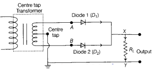
Question 18.
The wavelength λ of a photon and the de Broglie wavelength of
an electron of mass m have the same value. Show that the energy of the photon is
2λm c/h times, the kinetic energy of the electron, where c and h have their
usual meanings.
Answer:
Given, wave length of photon = wave length of
electron = λ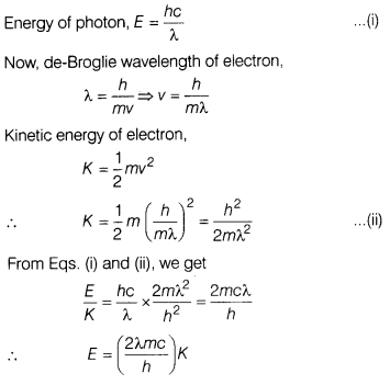
Question 19.
A ray of monochromatic light passes through an equilateral
glass prism in such a way that the angle of incidence is equal to the angle of
emergence and each of these angles is 3/4 times the angle of the prism.
Determine the angle of deviation and the refractive index of the glass
prism.
Answer:
Given, angle of incidence (i) = angle of emergence (e)
=
\(\frac{3}{4}\) A = \(\frac{3}{4}\) × 60°= 45°
If i = e, then there is
condition of δm.
∴ δm = 2i – A = 2 × 45° – 60°= 30°
∴ Refractive index of glass prism,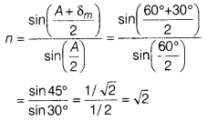
Question 20.
A heating element using nichrome connected to a 230 V supply
draws an initial current of 3.2 A which settles after a few seconds to a steady
value of 2.8 A. What is the steady temperature of the heating element, if the
room temperature is 27.0°C and the temperature coefficient of resistance of
nichrome is 1.70 × 10⁻⁴°C-1?
Answer:
Given, V =
230V, l0 = 3.2A , l = 2.8A, T0 = 27°C
α = 1.70 ×
10-4°C-1
Using equation R = R0( 1 + α ∆T)
i.e.
V/l = (V/l0)[1 + α ∆T]
and solving, ∆T = T – T0
= 840
i.e. T = 840 + 27 = 867°C
Question 21.
Show that the least possible distance between an object and
its real image in a convex lens is 4f, where i is the focal length of the
lens.
Or
In an astronomical telescope in normal adjustment, a straight
black line of length L is drawn on the objective lens. The eyepiece forms a real
image of this line whose length is l. What is the angular magnification of the
telescope?
Answer:
Let d be the least distance between object and image
for a real image formation.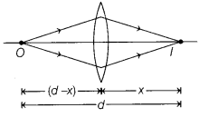
From lens formula,
\(\frac{1}{f}=\frac{1}{v}-\frac{1}{u}\)
⇒
\(\frac{1}{f}=\frac{1}{x}+\frac{1}{(d-x)}=\frac{d}{x(d-x)}\)
⇒ x² – dx + fd =
0
For real roots,
D ≥ 0
i.e. d² – 4fd ≥ 0
∵ d ≥ 4f
Or
Let f0 and fe be the focal lengths of the objective and
eyepiece, respectively.
For normal adjustment, the distance from objective to
eyepiece is f0 + fe.
Taking the line on the objective
as object and eyepiece as lens.
u = -(f0 + fe) and f =
fe.
\(\frac{1}{v}-\frac{1}{\left[-\left\{f_0+f_e\right\}\right]}=\frac{1}{f_e}\)
⇒ v = \(\left[\frac{f_0+t_e}{t_0}\right] f_0\)
Linear magnification
(eyepiece)
= \(\frac{v}{u}=\frac{\text { Image size }}{\text { Object size
}}=\frac{f_e}{f_0}=\frac{l}{L}\)
∴ Angular magnification of telescope,
M =
\(\frac{f_0}{f_e}=\frac{L}{l}\)
SECTION C
Question 22.
A given coin has a mass of 3.0 g. Calculate the nuclear
energy that would be required to separate all the neutrons and protons from each
other. For simplicity, assume that the coin is entirely made of \({ }_{29}^{63}
\mathrm{Cu}\) atoms (of mass 62.92960 u).
(Given, mp = 1.007825 u
and mn = 1.008665u).
Answer:
Number of atoms in 3 g of Cu
coin
= (6.023 × 1023 × 3) / 63 = 2.86 × 10²²
Each
atom has 29 protons and 34 neutrons.
Mass defect,
Am = [29 mp +
34mn – m(\({ }_{29}^{63} \mathrm{Cu}\))]c2
= (29 ×
1.007825 + 34 × 1.008665 – 62.92960)uc2
= 0.59225 × 931.5 MeV
Nuclear energy required for 3 g of Cu
= 0.59225 × 931.5 × 2.86 × 1022 MeV
= 1.58 × 1025 MeV
Question 23.
Charges +q and -q are placed at the points A and B
respectively, which are a distance 2L apart. C is the mid-point between A and B.
What is the work done in moving a charge +Q along the semi-circle CRD?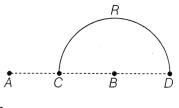
Answer: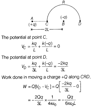
Question 24.
The total energy of an electron in the first excited state of
the hydrogen atom is about -3.4 eV
(i) What is the kinetic energy of the
felectron in this state?
(ii) What is the potential energy of the electron in
this state?
(iii) Which of the answers above would change, if the choice of
the zero of potential energy is changed?
Answer:
Given, E1 =
-3.4eV
(i) Kinetic energy, K = -E1 = 3.4eV
(ii) Potential
energy, U = -2K = -2 × 3.4eV = -6.8 eV
(iii) By changing reference point
(zero potential energy) for potential energy, the potential energy will
change.
As, E = \(-\frac{U}{2}\)
So, total energy will also change. There
is no any change in kinetic energy.
Question 25.
A wire of uniform cross-section and resistance 4 Ω is bent in
the shape of square ABCD. Point A is connected to a point P on DC by a wire AP
of resistance 1 Ω. When a potential difference is applied between A and C, the
points B and P are seen to be at the same potential. What is the resistance of
the part DP?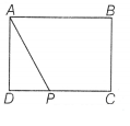
Answer: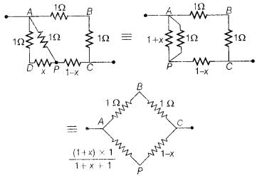 As the points B and P are at the same potential,
\(\frac{1}{1}=\frac{\frac{(1+x)}{(2+x)}}{(1+x)}\)
⇒ x = (√2-1)Ω
Question 26.
The given figure shows a long straight wire of a circular
cross-section (radius a) carrying steady current I. The current I is uniformly
distributed across this cross-section. Calculate the magnetic field in the
region r< a and r>a.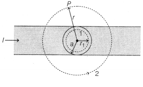
Answer:
From given figure in question
(i) Consider the
case r < a. The amperian loop is a circle labelled 1.
For this loop,
taking the radius of the circle to be r,
L = 2πr
Now, the current enclosed
ie is not i, but is less than this value.
Since, the current
distribution is uniform, the current enclosed,
ie = i(\(\frac{\pi
r^2}{\pi a^2}\)) = \(\frac{ir^2}{a^2}\)
Using Ampere’s law, B(2πr) =
μ0 \(\frac{ir^2}{a^2}\)
B = (\(\frac{μ_0 i}{2\pi a^2}\))r
⇒ B ∝
r (r < a) (ii) Consider the case r > a. The amperian loop, labelled 2, is
a circie concentric with the cross-section.
For this loop, L = 2πr
Using
Ampere circuital law, we can write
B(2πr) = μ0i
B = \(\frac{μ_0
i}{2\pi r}\)
⇒ B ∝ \(\frac{1}{r}\) (r > a)
Question 27.
Identify the part of the electromagnetic spectrum which
(i) produces heating effect,
(ii) is absorbed by the ozone layer in the
atmosphere,
(iii) is used for studying crystal structure.
Write any one
method of the production of each of the above radiations.
Answer:
(i)
Infrared produces heating effect.
(ii) Ultraviolet ray is absorbed by the
ozone layer in the atmosphere.
(iii) X-ray is used to study crystal
structure.
Method of the production
(i) Infrared is produced by a
non-luminous generator in which an electric current is passed through a
coil.
(ii) Ultraviolet ray is produced by mercury-vapour lamp.
(iii) X-ray
is produced by acceleration of electron through a certain potential
difference.
Question 28.
(i) Define mutual inductance and write its SI unit.
(ii)
Two circular loops, one of small radius r and other of large radius R, such that
R >> r are placed co-axially with centres coinciding. Obtain the mutual
inductance of the arrangement.
Or
Two long straight parallel current
carrying conductors are kept a distant apart in air. The direction of current in
both the conductors is same. Find the magnitude of force per unit length and
direction of the force between them. Hence, define one ampere.
Answer:
(i)
Mutual induction is defined as the the property of the coil that opposes the
change in current in another coil. Its SI unit is henry (H) or Tm²/A.
(ii)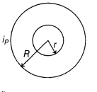
Let a current iP flows through the circular loop
of radius R. The magnetic induction at the centre of the loop,
BP
= \(\frac{\mu_0 i_p}{2 R}\)
As r << R, the magnetic induction BP may be considered to be
constant over the entire cross-sectional area of inner loop of radius r. Hence,
magnetic flux linked with the smaller loop will be
ϕS =
BPAS = \(\frac{\mu_0 i_p}{2 R}\) πr²
Also,
ϕS = MiP
M = \(\frac{\phi_S}{i_P}=\frac{\mu_0 \pi
r^2}{2 R}\)
Or
The magnetic induction set-up by the current l1,
flowing in first conductor at a point somewhere in the middle of second
conductor,
B1 = \(\frac{\mu_0 i_1}{2 \pi a}\) …….(i)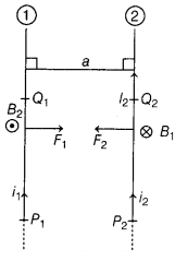
The magnetic force acting on the portion
P2Q2 of length l2 of second conductor,
F2 = i2l2B2 sin 90° …..(ii)
From
Eqs. (i) and (ii), we get
F2 = \(\frac{\mu_0 i_1 i_2 l_2}{2 \pi
a}\)
\(\frac{F_2}{l_2}=\frac{\mu_0 i_1 i_2}{2 \pi a}\) ………(iii)
The magnetic induction B2 set-up by the current l2
flowing in second conductor at a point somewhere in the middle of first
conductor,
B2 = \(\frac{\mu_0 i_2}{2 \pi a}\) …….(iv)
The
magnetic force acting on the portion P1Q1 of length
l1, of first conductor,
F1 =
i1l1B2 sin 90° …..(v)
From Eqs. (iii) and
(v), we get
F1 = \(\frac{\mu_0 i_1 i_2 l_1}{2 \pi a}\) towards
second conductor
\(\frac{F_1}{l_1}=\frac{\mu_0 i_1 i_2}{2 \pi a}\)
……..(vi)
The standard definition of 1 A
lf i1 = i2 = 1A,
l1 = l2 = 1m
and a = 1 m in V/A, then
\(\frac{F_1}{l_1}=\frac{F_2}{l_2}=\frac{\mu_0 \times 1 \times 1}{2 \pi \times
1}\)
= 2 × 10⁻⁷ N/m
∴ One ampere is that electric current which
when flows in each one of the two infinitely long straight parallel conductors
placed 1 m apart in vacuum causes each one of them to experience a force of 2 ×
10-7 N/m.
SECTION D
Question 29.
Read the following paragraph and answer the questions that
follows.
A semiconductor diode is basically a p-n junction with metallic
contacts provided at the ends for the application of an external voltage. It is
a two terminal device. When an external voltage is applied across a
semiconductor diode, such that p-side is connected to the positive terminal of
the battery and n-side to the negative terminal, it is said to be forward
biased. Whan an external voltage is applied across the diode, such that n-side
is positive and p-side is negative, it is said to be reverse biased.
An ideal
diode is one whose resistance in forward biasing is zero and the resistance is
infinite in reverse biasing. When the diode is forward biased, it is found that
beyond forward voltage called knee voltage, the conductivity is very high. When
the biasing voltage is more than the knee voltage, the potential barrier is
overcome and the current increases rapidly with increase in forward voltage.
When the diode is reverse biased, the reverse bias voltage produces a very small
current about a few microamperes which almost remains constant with bias. This
small current is reverse saturation current.
(i) In the given figure, a diode
D is connected to an external resistance R = 100 Ω and an emf of 3.5 V If the
barrier potential developed across the diode is 0.5 V the current in the circuit
will be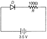
(a) 40 mA
(b) 20 mA
(c) 35 mA
(d) 30 mA
Answer:
(d) 30 mA
The circuit is represented by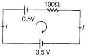
∴ Applying KVL in the loop, 3.5 – 0.5 -100 l = 0
∴ l = 30
mA
(ii) In which of the following figures, the p-n diode is reverse
biased?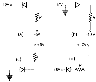 Answer:
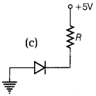 n-side terminal of the diode is connected to negative potential. So, it is
reversed biased.
n-side terminal of the diode is connected to negative potential. So, it is
reversed biased.
(iii) Based on the V-I characteristics of the diode, we can classify diode
as
(a) bilateral device
(b) ohmic device
(c) non-ohmic device
(d)
passive element
Answer:
(c) non-ohmic device
Based on V-I characteristics, the diode is classified as non-ohmic
device.
Or
Two identical p-n junctions can be connected in series by three
different methods as shown in the figure. If the potential difference in the
junctions is the same, then the correct connections will be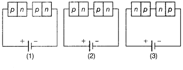 (a) in the circuits (1) and (2)
(b) in the circuits (2) and (3)
(c) in the
circuits (1) and (3)
(d) only in the circuit (1)
Answer:
(b) in the
circuits (2) and (3)
For series combination of diode n- side of one diode is connected to p-side of other diode and vice-versa.
(iv) The V-i characteristic of a diode is shown in the figure. The ratio of
the resistance of the diode at i = 15 mA to the resistance at V = -10 V
is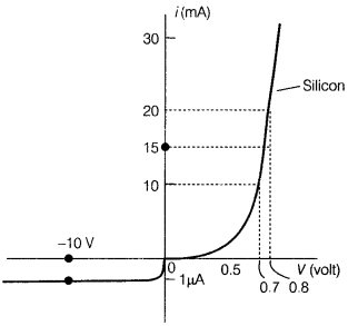 (a) 100
(b) 106
(c) 10
(d) 10-6
Answer:
(d)
10-6
Rf = Resistance of diode
at l = 15 mA = \(\frac{V_f}{i_f}\) =
\(\frac{(0.75-0.7)}{(15 – 10)×10^-3}\) = 10
Rb = Resistance of
diode at V = -10V
= \(\frac{V_b}{i_b}\) = \(\frac{10}{10^-6}\) =
107
∴ \(\frac{R_f}{R_b}\) = \(\frac{10}{10^7}\) =
10-6
Question 30.
Read the following paragraph and answer the questions that
follow.
Types of Lenses and their combination
A convex or converging lens is
thicker at the centre than at the edges. It converges a beam of light on
refraction through it. It has a real focus. Convex lens is of three types :
Double convex lens, Plano-convex lens and Concavo-convex lens.
Concave lens
is thinner at the centre than at the edges. It diverges a beam of light on
refraction through it. It has a virtual focus. Concave lenses are of three types
: Double concave lens. Plano-concave lens and Convexo-concave lens.
When two
thin lenses of focal lengths f1 and f2 are placed in
contact with each other along their common principal axis, then the two lens
system is regarded as a single lens of focal length f and
\(\frac{1}{f}=\frac{1}{f_1}+\frac{1}{f_2}\)
If several thin lenses of focal
lengths f1, f2, …… fn are placed in contact,
then the effective focal length of the combination is given by
\(\frac{1}{f}=\frac{1}{f_1}+\frac{1}{f_2}+\ldots+\frac{1}{f_n}\)
and, in
terms of power, we can write
P = P1 + P2+ …
+Pn
The value of focal length and power of a lens must be used
with proper sign consideration.
(i) Two thin lenses are kept co-axially in
contact with each other and the focal length of the combination is 80 cm. If the
focal length of one lens is 20 cm, the focal length of the other would be
(a)
-26.7 cm
(b) 60 cm
(c) 80 cm
(d) 30 cm
Answer:
(a) -26.7 cm
Given, f = 80 cm, f1 = 20 cm
For combination of lens,
\(\frac{1}{f}=\frac{1}{f_1}+\frac{1}{f_2}\)
\(\frac{1}{8}=\frac{1}{20}+\frac{1}{f_2}\)
f2 = -26.7 cm
(ii) A spherical air bubble is embedded in a piece of glass. For a ray of
light passing through the bubble, it behaves like a
(a) converging lens
(b) diverging lens
(c) mirror
(d) thin plane sheet of glass
Answer:
(b) diverging lens
A spherical air bubble embedded in a piece of glass behaves as a diverging lens.
(iii) Lens generally used in magnifying glass is
(a) single concave
lens
(b) single convex lens
(c) combination of convex lens of lower power
and concave lens of lower focal length
(d) plano-concave lens
Answer:
(b) single convex lens
Single convex lens is used in magnifying glass.
(iv) The magnification of an image by a convex lens is positive only when the
object is placed
(a) at its focus F
(b) between F and 2F
(c) at 2F
(d) between F and optical centre
Answer:
(d) between F and optical
centre
The magnification of an image by convex lens is positive only when the object
is placed between focal point (F) and optical centre, because image formed by
the convex lens for this location object is virtual and magnified and for real
image, m = – ve.
For virtual image, m = + ve.
Or
A convex lens of 20 cm focal length forms a real image which is three times
magnified. The distance of the object from the lens is
(a) 13.33 cm
(b) 14
cm
(c) 26.66 cm
(d) 25 cm
Answer:
(c) 26.66 cm
Given, f + 20 cm, m = -3 = \(\frac{v}{u}\)
= v = -3u
By lens formula,
\(\frac{1}{v}-\frac{1}{u}=\frac{1}{f}\)
\(\frac{1}{-3
u}-\frac{1}{u}=\frac{1}{20}\)
u = -26.66 cm
∴ Distance of the object =
-26.66 cm
SECTION E
Question 31.
(i) Draw a ray diagram for the formation of image of a point
object by a thin double convex lens having radii of curvature R1 and
R2. Hence, derive lens Maker’s formula.
(ii) A converging lens has
a focal length of 10 cm in air. It is made of a material of refractive index
1.6. If it is immersed in a liquid of refractive index 1.3, find its new focal
length.
Or
(i) Define a wavefront. How is it different from a ray?
(ii)
Using Huygens’ construction of secondary wavelets, draw a diagram showing the
passage of a plane wavefront from a denser to a rarer medium. Using it verify
Snell’s law.
(iii) In a double slit experiment, using light of wavelength 600
nm and the angular width of the fringe formed on a distant screen is 0.1°. Find
the spacing between the two slits.
(iv) Write two differences between
interference pattern and diffraction pattern.
Answer:
(i) Lens Maker’s
formula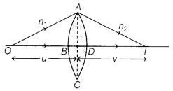
When a ray refracts from a lens (double convex), in above
figure, then its image formation can be seen in term of two steps:
Step 1 The
first refracting surface forms the image l1, of the object O.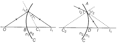
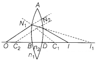
Step 2 The image of object 0 for first surface acts like a
virtual objects for the second surface. Now for the first surface ABC, ray will
move from rarer to denser medium, then
\(\frac{n_2}{B l_1}+\frac{n_1}{O
B}=\frac{n_2-n_1}{B C_1}\) ……….(i)
Similarly for the second interface ADC, we
can write
\(\frac{n_1}{D l}-\frac{n_2}{D l_1}=\frac{n_2-n_1}{D C_2}\)
…………(ii)
Dl1 is negative as distance is measured against the
direction of incident light.
Adding Eqs. (i) and (ii), we get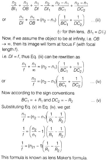 (ii) Given, for a converging lens,
fa = 10 cm, ul =
1.6, um =1.3
By lens Maker’s formula,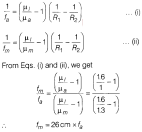
Or
(i) A surface on which the wave disturbance is in same phase at all points is
called wavefront.
A wavefront is different from a ray in following manner
(a) The ray indicates the direction of propagation of • wave, while the
wavefront is the surface of
constant phase.
(b) The ray at each point of a
wavefront is normal to the wavefront at the point.
(ii) Consider AS is
incident plane wavefront and CE is refracted wavefront.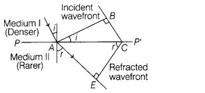
where, n1v1 = refractive index and
speed of light of first medium
n2v2 = refractive index
and speed of light of second medium.
From the diagram,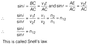 (iii) Given, λ = 600 nm = 600 × 10-9m
Angular width, θ = 0.1° =
0.1 × \(\frac{\pi}{180}\) rad
∴ Angular width (θ) is given by
θ =
\(\frac{λ}{a}\)
∴ a = \(\frac{λ}{θ}\) = \(\frac{600 \times 10^{-9}}{0.1
\times \frac{\pi}{180}}\)
= 3.4 × 10⁻⁷
(iv) Two differences
between interference pattern and diffraction pattern are as follow
Table
1
Interference
Interference fringes are formed, when the two light rays
from the coherent sources are superimposed.
All bright fringes are equally
illuminated.
Diffraction
Diffraction fringes are formed due to superposition of light
rays from the same source.
Central fringe is brightest and all other fringes
have intensity in decreasing order.
Question 32.
(i) Derive an expression for the capacitance of a parallel
plate capacitor with air present between the two plates.
(ii) Obtain the
equivalent capacitance of the network shown in figure. For a 300 V supply,
determine the charge on each capacitor.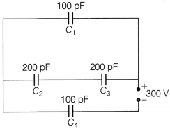
Or
(i) A dielectric slab of thickness t is kept between
the plates of a parallel plate capacitor with plate separation d (t < d).
Derive the expression for the ‘capacitance of the capacitor.
(ii) A capacitor
of capacity C1 is charged to the potential of V0. On
disconnecting with the battery, it is connected with an uncharged capacitor of
capacity C2 as shown in the figure. Find the ratio of energies before
and after the connection of switch S.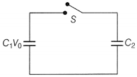
Answer:
(i) Let the two plates be kept parallel to each
other separated by a distance d and cross-sectional area of each plate is
A.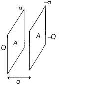
Electric field by a single thin plate, E =
σ/2ε0
Total electric field between the plates, E
=
σ/2ε0 = Q/Aε0
Potential difference between the
plates,
V = Ed = [Q/Aε0]d
Capacitance, C = Q/V =
Aε0/d
(ii)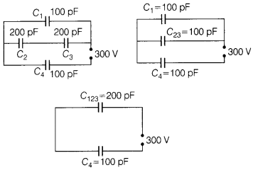 The equivalent capacitance = \(\frac{200}{3}\) pF
Charge on C4 =
\(\frac{200}{3}\) × 10-12 × 300 = 2 × 10⁻⁸ C
Potential
difference across C4
= \(\frac{200×10^-12×300}{3×100×10^-12}\) =
200V
Potential difference across,
C1 = 300 – 200 = 100V
Charge on C1 =100 × 10-12 × 100
= 1 × 10⁻⁸
C
Potential difference across C2 and C3 series
combination = 100 V
Potential difference across C2 and
C3 each = 50 V
Charge on C2 and C3 each
=
200 × 10-12 × 50
= 1 × 10⁻⁸ C
Or
(i)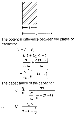
(ii)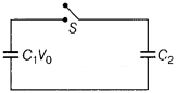
Before the connection of switch S, initial energy,
Ui = \(\frac{1}{2}\) C1v02 +
\(\frac{1}{2}\) C2v02 = \(\frac{1}{2}\)
C1v02
After the connection of switch S
common potential,
Question 33.
(i) Draw graphs showing the variations of inductive reactance
and capacitive reactance with frequency of applied AC source.
(ii) Draw the
phasor diagram for a series L-C-R circuit connected to an AC source.
(iii)
When an alternating voltage of 220V is applied across a device X, a current of
0.25A flows which lags behind the applied voltage in phase by (π/2) rad. If the
same voltage is applied across another device Y, the same current flows but now
it is in phase with the applied voltage.
(a) Name the devices X and Y.
(b)
Calculate the current flowing in the circuit, when the same voltage is applied
across the series combination of X and Y.
Or
(i) A series L-C-R circuit is
connected to an AC source. Using the phasor diagram, derive the expression for
the impedance of the circuit.
(ii) Plot a graph to show the variation of
current with frequency of the AC source, explaining the nature of its variation
for two different resistances R1 and R2 (R1
< R2) at resonance.
Answer:
(i) The graphs of inductive
reactance (XL) and capacitive reactance (XC) with
frequency are given below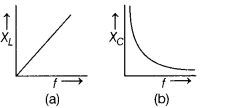
(ii) The phasor diagram for series L-C-R circuit connected with AC is given
below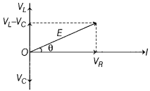
(iii) (a) In device X, current lags behind the voltage by π/2, X is an
inductor. In device X current in phase with the applied voltage, Y is
resistor.
(b)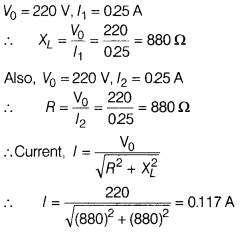
Or
(i)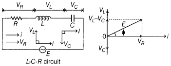 The voltage applied, E = E0 sin ωt
The voltage across L, C and R
is given by
VL = i XL, VC = i
XC
and VR = i R
From the phasor diagram,
E2 = (VL – VC)2 + VR
=
i2[R2 + (XL-XC)2]
E =
i\(\sqrt{R^2+\left(X_L-X_C\right)^2}\)
The impedance of the circuit is given
by
z = \(\frac{E}{i}\) = \(\sqrt{R^2+\left(X_L-X_C\right)^2}\)
tan ϕ =
\(\frac{V_L-V_C}{V_R}\) = \(\frac{X_L-X_C}{R}\)
(ii) The graph for the variation of current with frequency of AC source is
given below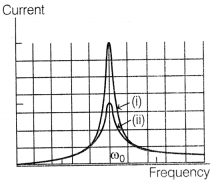
The curve (i) is for R1 and the curve (ii) is for
R2, where (R1 < R2).