Alternating Current
Class 12th Physics Chapter Important Questions
Class 12 Physics Chapter 7 Important Extra Questions Alternating Current
Very Short Answer
Question 1.
The instantaneous current and voltage of an a.c. circuit are
given by i = 10 sin 300 t A and V = 200 sin 300 t V. What is the power
dissipation in the circuit? (All India 2008)
Answer: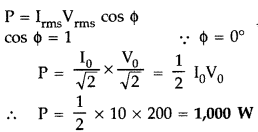
Question 2.
The instantaneous current and voltage of an a.c. circuit are
given by i = 10 sin 314 t A and v = 50 sin 314 t V. What is the power
dissipation in the circuit? (All India 2008)
Answer:![]()
Question 3.
The instantaneous current and voltage of an a.c. circuit are
given by i = 10 sin 314 tA and v = 50 sin \(\left(314 t+\frac{\pi}{2}\right)\)V.
(All India 2008)
Answer:![]()
Phase difference between current voltage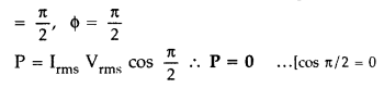
Question 4.
Define the term ‘wattless current’. (Delhi 2011)
Answer:
Wattless current is that component of the circuit current due to
which the power consumed in the circuit is zero.
Question 5.
Mention the two characteristic properties of the material
suitable for making core of a transformer. (All India 2012)
Answer:
Characteristic properties of material suitable for core of a transformer :
- It should have high permeability
- It should have low hysteresis loss.
- It should have low coercivity/retentivity.
- It should have high resistivity. (Any two)
Question 6.
When an ac source is connected across an ideal inductor, show
on a graph the nature of variation of the voltage and the current over one
complete cycle. (Comptt. Delhi 2012)
Answer: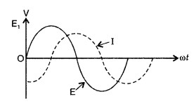
Question 7.
A heating element is marked 210 V, 630 W. What is the value of
the current drawn by the element when connected to a 210 V dc source? (Delhi
2013)
Answer:![]()
Question 8.
A heating element is marked 210 V, 630 W. Find the resistance
of the element when connected to a 210 V dc source.
Answer: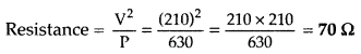
Question 9.
Why is the core of a transformer laminated? (Comptt. Delhi
2013)
Answer:
The core of a transformer is laminated to minimize eddy
currents in the iron core.
Question 10.
Why is the use of a.c. voltage preferred over d.c. voltage?
Give two reasons. (All India 2013)
Answer:
a.c. voltage is preferred over
d.c. voltage because of following reasons :
- it can be stepped-up or stepped-down by a transformer.
- carrying losses are much less.
Question 11.
Define capacitor reactance. Write its S.I. units. (Delhi
2015)
Answer:
‘Capacitor reactance’ is defined as the opposition to the
flow of current in ac circuits offered by a capacitor.![]()
S.I. Unit : Ohm.
Question 12.
A variable frequency AC source is connected to a capacitor.
Will the displacement current change if the frequency of the AC source is
decreased? (Comptt. All India 2015)
Answer:
On decreasing the frequency of
AC source, reactance, \(x_{C}=\frac{1}{\omega C}\) will increase, which will
lead to decrease in conduction current. In this case
ID =
IC
Hence, displacement current will decrease.
Question 13.
Plot a graph showing variation of capacitive reactance with
the change in the frequency of the AC source. (Comptt. All India 2015)
Answer:
Graph showing a variation of xc capacitive reactance with
the change in frequency of AC source.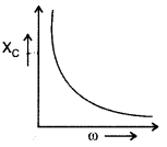
Question 14.
Define ‘quality factor’ of resonance in series LCR circuit.
What is its SI unit? (Delhi 2016)
Answer:
Quality factor (Q) is defined
as, Q = \(\frac{\omega_{0} L}{R}\)
It gives the sharpness of the resonance
circuit. It has no SI unit.
Question 15.
For an ideal inductor, connected across a sinusoidal ac
voltage source, state which one of the following quantity is zero :
(i)
Instantaneous power
(ii) Average power over full cycle of the ac voltage
source
Answer:
Average power over full cycle of
the ac voltage source is zero, when connected with an ideal inductor.
Question 16.
The instantaneous current flowing from an ac source is l = 5
sin 314 t. What is the rms value of current?
Answer:
The rms value of
current is \(\frac{5}{\sqrt{2}}\).
Question 17.
The instantaneous emf of an ac source is given by E = 300 sin
314 t. What is the rms value of emf?
Answer:
The rms value of voltage is
\(\frac{300}{\sqrt{2}}\)
Question 18.
Give the phase difference between the applied ac voltage and
the current in an LCR circuit at resonance.
Answer:
The applied ac voltage
and the current in an LCR circuit at resonance are in phase.
Hence phase
difference = 0.
Question 19.
What is the phase difference between the voltage across the
inductor and the capacitor in an LCR circuit?
Answer:
The phase difference
is 180°.
Question 20.
What is the power factor of an LCR series circuit at
resonance?
Answer:
The power factor is one.
Question 21.
In India, the domestic power supply is at 220 V, 50 Hz, while
in the USA it is 110 V, 50 Hz. Give one advantage and one disadvantage of 220 V
supply over 110 V supply.
Answer:
Advantage: less power loses
Disadvantage: more fatal.
Question 22.
Define the term ‘wattles current’. (CBSE Delhi 2011)
Answer:
It is the current at which no power is consumed.
Question 23.
In a series LCR circuit, VL = VC ≠
VR. What is the value of the power factor? (CBSE AI 2015)
Answer:
One.
Question 24.
Define capacitor reactance. Write its SI units. (CBSE Delhi
2015)
Answer:
It is the opposition offered to the flow of current by a
capacitor. It is measured in ohm.
Question 25.
Define quality factor in series LCR circuit. What is its SI
unit? (CBSE Delhi 2016)
Answer:
The quality factor is defined as the ratio
of the voltage developed across the capacitor or inductor to the applied
voltage. It does not have any unit.
Question 26.
A choke and a bulb are in series to a dc source. The bulb
shines brightly. How does its brightness change when an iron core is inserted
inside the choke coil?
Answer:
There is no change in the final brightness
as the inductive reactance is zero for dc.
Question 27.
A solenoid with an iron core and a bulb are connected to a dc
source. How does the brightness of the bulb change, when the iron core is
removed from the solenoid?
Answer:
There Is no change In the finaL
brightness as the inductive reactance is zero for dc.
Question 28.
In a serles LCR circult, the voltage across an inductor,
capacitor and a resistor are 20 V, 20 V and 40 V, respectively. What Is the
phase difference between the applied voltage and the current In the circuit?
Answer:
WhenVL = VC, then the circuit is in series
resonance, therefore both current and voltage are in phase.
Question 29.
Why Is there no power consumption In an Ideal inductor
connected to an ac source?
Answer:
This is because current and voltage
across an ideal inductor are out of phase by 900.
Hence P = VRMS
IRMS cos 90° = O
Question 30.
Can a choke be replaced by a capacitor of suitable
capacitance?
Answer:
Yes, because even then the power consumed will be
zero.
Question 31.
Find the inductance of the Inductor that would have a
reactance of 50 ohm when used with an ac source of frequency 25/π kHz.
Answer:
Using XL = 2 πf L or L = \(\frac{X_{L}}{2 \pi f}\),
therefore
L = \(\frac{50 \times \pi}{2 \pi \times 25}\) = 1 H
Question 32.
The figure gIven below shows the variation of an alternating
emf with time. What Is the average value of the emf for the shaded part of the
graph?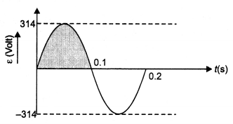
Answer:
Average or mean value of ac over half cycle or in time T/2 is
Em = 2Eo/π = 0.637 Eo = 0.637 × 314
or Em =
200 V.
Question 33.
What is the power dissipated in an ac circuit in which the
voltage and current are given by V = 230 sin(ωt + π/2) and l = 10 sin ωt.
Answer:
Since the phase difference between the voltage and current is π/2,
therefore power consumed = Vrms lrms cos π/2 = 0
Question 34.
When a lamp is connected to an alternating voltage supply, it
lights with the same brightness as when compared to a 12 V dc battery. What Is
the peak value of alternating voltage?
Answer:
The peak value is V = 12 ×
\(\sqrt{2}\) = 16.97 V
Question 35.
Why is the use of a.c. voltage preferred over d.c. voltage?
Give two reasons. (CBSEAI 2014)
Answer:
- Can be increased or decreased easily.
- Can easiLy be converted into dc.
Question 36.
Can the Instantaneous power output of an ac source ever be
negative? Can the average power output be negative?
Answer:
Yes, No.
Short Answer Type
Question 1.
State the phase relationship between the current flowing and
the voltage applied in an ac circuit for (i) a pure resistor (ii) a pure
inductor.
Answer:
- Electric current and voltage applied in a pure resistor are in same phase, i.e. Φ = 0°
- Applied voltage leads electric current flowing through pure-inductor in an ac circuit by phase angle of π/2.
Question 2.
A light bulb is in turn connected in a series (a) across an LR
circuit, (b) across an RC circuit, with an ac source. Explain, giving the
necessary mathematical formula, the effect on the brightness of the bulb in case
(a) and (b), when the frequency of the ac source is increased. (CBSE 2019C)
Answer:
(a) The current in LR circuit is given by
l =
\(\frac{V}{\sqrt{R^{2}+\omega^{2} L^{2}}}\)
When the frequency of ac source ω increases, l decreases, and hence brightness decreases.
(b) The current in RC circuit is given by
l =
\(\frac{V}{\sqrt{R^{2}+\frac{1}{\omega^{2} C^{2}}}}\)
When the frequency of ac source ω increases, l increases, and hence brightness increases.
Question 3.
An air-core solenoid is connected to an ac source and a bulb.
If an iron core is inserted in the solenoid, how does the brightness of the bulb
change? Give reasons for your answer.
Answer:
Insertion of an iron core in
the solenoid increases its inductance. This in turn increases the value of
inductive reactance. This decreases the current and hence the brightness of the
bulb.
Question 4.
A bulb and a capacitor are connected in series to an ac source
of variable frequency. How will the brightness of the bulb change on increasing
the frequency of the ac source? Give reason.
Answer:
When the frequency of
the ac is increased, it will decrease the impedance of the circuit as Z =
\(\sqrt{R^{2}+(1 / 2 \pi f C)^{2}}\). As a result, the current and hence the
brightness of the bulb will increase.
Question 5.
Prove that an ideal capacitor in an a.c. circuit does not
dissipate power. (Delhi 2008)
Answer:
Average power associated with a
capacitor :
When an a.c. is applied to a capacitor, the current leads the
voltage in phase by \(\frac{\pi}{2}\)radian. So we write the expressions for
instantaneous voltage and current as follows :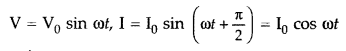
Work done in the circuit in small time dt will be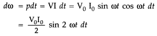
The average power dissipated per cycle in the capacitor is,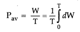
Thus the average power dissipated per cycle in a capacitor is zero.
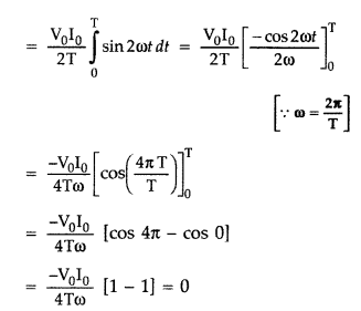
Question 6.
Prove that an ideal inductor does not dissipate power in an
a.c. circuit. (Delhi 2016)
Answer:
Average power associated with an
inductor.
When a.c. is applied to an ideal inductor,current lags behind the
voltage in phase by \(\frac{\pi}{2}\) radian. So we can write the instantaneous
values of voltage and current as follows :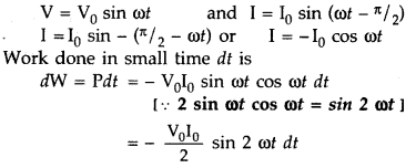
The average power dissipated per cycle in the inductor is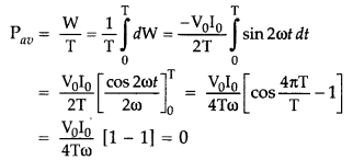
Thus, the average power dissipated per cycle in an inductor is zero.
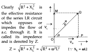
Question 7.
Derive an expression for the impedance of an a.c. circuit
consisting of an inductor and a resistor. (Delhi 2008)
Answer:
From the
phasor diagram, we get R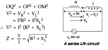
Thus the average power dissipated per cycle in a capacitor is zero.
Question 8.
The circuit arrangement as shown in the diagram shows that
when an a.c. passes through the coil A, the current starts flowing in the coil
B.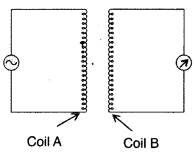
(i) State the underlying principle involved.
(ii) Mention
two factors on which the current produced in the coil B depends.(All India
2008)
Answer:
(i) It is based on the principle of “mutual induction”.
(ii) Two factors are:
- distance between the coils.
- orientation of the coils.
- Number of turns in the coil, (any two)
Question 9.
The figure given shows an arrangement by which current flows
through the bulb (X) connected with coil B, when a.c. is passed through coil
A.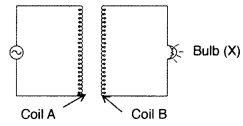
(i) Name the phenomenon involved.
(ii) If a copper sheet
is inserted in the gap between the coils, explain, how the brightness of the
bulb would change. (All India 2008)
Answer:
(i) The phenomenon involved is
mutual induction.
(ii) When the copper sheet is inserted, eddy currents are
set up in it which opposes the passage of magnetic flux. The induced emf in coil
B decreases. This decreases the brightness of the bulb.
Question 10.
A 15.0 µF capacitor is connected to 220 V, 50 Hz source. Find
the capacitive reactance and the rms current. (All India 2009)
Answer: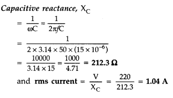
Question 11.
An electric lamp having coil of negligible inductance
connected in series with a capacitor and an a.c. source is glowing with certain
brightness. How does the brightness of the lamp change on reducing the
(i)
capacitance, and
(ii) the frequency? Justify your Answer. (Delhi
2009)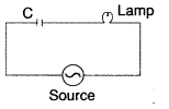
Answer:
Brightness of lamp \(\propto\) I0,
Assuming zero resistance and zero inductance of lamp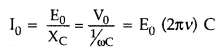
On reducing C or v; It would decrease
∴ Brightness of the
lamp will decrease.
Question 12.
State the principle of working of a transformer. Can a
transformer be used to step up or step down a d.c. voltage? Justify your Answer.
(All India 2009)
Answer:
Transformer works on the principle of mutual
induction, i.e., when a changing current is passed through one of the two
inductively coupled coils, an induced emf is set up in the other coil.
No, transformer cannot be used to step up or step down a d.c. voltage because d.c. voltage cannot produce a change in magnetic flux.
Question 13.
Mention various energy losses in a transformer. (All India
2009)
Answer:
(i) A transformer is an electrical device for converting an
alternating current at low voltages into that at high voltage or vice versa.
If it increases the input voltage, it is called step- up-transformer.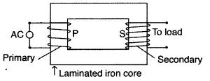
Principle : It works on the principle of mutual induction
i.e., “when a changing current is passed through one of the two inductively
coupled coils, an induced emf is set up in the other coil.”
Working : As the alternating current flows through the primary, it generates
an alternating magnetic flux in the core which also passes through the
secondary. This changing flux sets up an induced emf in the secondary, also a
self- induced emf in the primary. If there is no leakage of magnetic flux, then
flux linked with each turn
of the primary will be equal to that linked with
each turn of the secondary.![]()
…where
[Np and Ns are number of turns in the primary and
secondary respectively,
Vp and Vs are their respective
voltages]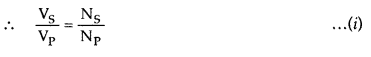
This ratio \(\frac{\mathrm{N}_{\mathrm{S}}}{\mathrm{N}_{\mathrm{P}}}\) is called
the turns ratio.
Assuming the transformer to be ideal one, so that there are
no energy losses, then
Input power = output power
Vplp = VSIS
…where [IP
and IS are the current in the primary and secondary
respectively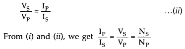
In a step up transformer, Ns > Np i.e., the turns
ratio is greater than 1 and therefore Vs > Vp.
The
output voltage is greater than the input voltage.
Main assumptions :
- The primary resistance and current are small.
- The same flux links both with the primary and secondary windings as the flux leakage from due core is negligible (small).
- The terminals of the secondary are open or the current taken from it, is small, (any two)
For long distance transmission, the voltage output of the generator is stepped-up (so that current is reduced and consequently, IR loss is reduced). It is transmitted over long distance and is stepped- down at distributing substations at consumers’ end.
(ii) Two sources of energy loss in a transformer:
1. Copper loss”: Some
energy is lost due to heating of copper wires used in the primary and secondary
windings. This power loss (= I2R) can be minimised by using thick
copper wires of low resistance.
2. Eddy current loss : The alternating magnetic flux induces eddy currents in the iron core which leads to some energy loss in the form of heat. This loss can be reduced by using laminated iron core.
(iii) No, a step up transformer does not violate law of conservation of energy because whatever is gained in voltage ratio is lost in the current ratio and vice-versa. It steps up the voltage while it steps down the current.
Question 14.
State the underlying principle of a transformer.
How is
the large scale transmission of electric energy over long distances done with
the use of transformers? (All India 2012)
Answer:
A transformer is an
electrical device for converting an alternating current at low voltages into
that at high voltage or vice versa.
If it increases the input voltage, it is
called step- up-transformer.
Principle : It works on the principle of mutual induction
i.e., “when a changing current is passed through one of the two inductively
coupled coils, an induced emf is set up in the other coil.”
Working : As the alternating current flows through the primary, it generates
an alternating magnetic flux in the core which also passes through the
secondary. This changing flux sets up an induced emf in the secondary, also a
self- induced emf in the primary. If there is no leakage of magnetic flux, then
flux linked with each turn
of the primary will be equal to that linked with
each turn of the secondary.![]()
…where
[Np and Ns are number of turns in the primary and
secondary respectively,
Vp and Vs are their respective
voltages]
This ratio \(\frac{\mathrm{N}_{\mathrm{S}}}{\mathrm{N}_{\mathrm{P}}}\) is called
the turns ratio.
Assuming the transformer to be ideal one, so that there are
no energy losses, then
Input power = output power
Vplp = VSIS
…where [IP
and IS are the current in the primary and secondary
respectively
In a step up transformer, Ns > Np i.e., the turns
ratio is greater than 1 and therefore Vs > Vp.
The
output voltage is greater than the input voltage.
Main assumptions :
- The primary resistance and current are small.
- The same flux links both with the primary and secondary windings as the flux leakage from due core is negligible (small).
- The terminals of the secondary are open or the current taken from it, is small, (any two)
For long distance transmission, the voltage output of the generator is stepped-up (so that current is_ reduced and consequently, IR loss is reduced). It is transmitted over long distance and is stepped- down at distributing substations at consumers’ end.
Question 15.
A light bulb is rated 100 W for 220 V ac supply of 50 Hz.
Calculate
(i) the resistance of the bulb;
(ii) the rms current through the
bulb. (All India 2012)
Answer: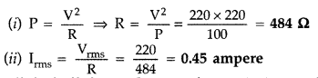
Question 16.
A light bulb is rated 200 W for 220 V ac supply of 50 Hz.
Calculate
(i) the resistance of the bulb;
(ii) the rms current through the
bulb. (All India 2012)
Answer:
Hint: (i) 242Ω
(ii) Irms = 0.90 atmosphere
Question 17.
A light bulb is rated 150 W for 220 V ac supply of 60 Hz.
Calculate
(i) the resistance of the bulb; ,
(ii) the rms current through
the bulb. (All India 2012)
Answer:
Hint :
(i) P = 322.67 Ω
(ii) Irms = 0.68 ampere
Question 18.
An alternating voltage given by V = 140 sin 314 t is
connected across a pure resistor of 50 Ω. Find
(i) the frequency of the
source.
(ii) the rms current through the resistor. (All India 2012)
Answer:
Question 19.
An alternating voltage given by V = 280 sin 50πt is connected
across a pure resistor of 40 Ω. Find
(i) the frequency of the source.
(ii)
the rms current through the resistor. (All India 2012)
Answer:
Hint:
(i) v = 25 Hz
(ii) Irms = 4.95 A
Question 20.
An alternating voltage given by V = 70 sin 100πt is connected
across a pure resistor of 25 Ω . Find
(i) the frequency of the source.
(ii) the rms current through the resistor. (All India 2012)
Answer:
(i) v = 50Hz
(ii) Irms = 1.98 Ampere.
Question 21.
A lamp is connected in series with a capacitor. Predict your
observation when this combination is connected in turn across
(i) ac source
and
(ii) a ‘dc’ battery. What change would you notice in each case if the
capacitance of the capacitor is increased? (Comptt. Delhi 2012)
Answer:
When dc source is connected, the condenser is charged but no current flows in
the circuit, therefore, the lamp does not glow. No change occurs even when
capacitance of capacitor is increased.
When ac source is connected, the capacitor offers capacitive reactance \(X_{c}=\frac{1}{\omega C}\). The current flows in the circuit and the lamp glows. On increasing capacitance, Xc decreases. Therefore, glow pf the bulb increases.
Question 22.
A capacitor ‘C’, a variable resistor ‘R’ and a bulb ‘B’ are
connected in series to the ac mains in a circuit as shown. The bulb glows with
some brightness. How will the glow of the bulb change if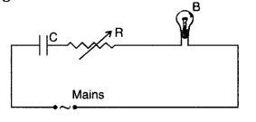
(i) a dielectric slab is introduced between the plates of the
capacitor, keeping resistance R to be the same;
(ii) the resistance R is
increased keeping the same capacitance? (Delhi 2012)
Answer:
(i)
Brightness will increase due to increase in capacitance on introducing
dielectric slab.
(ii) Brightness will decrease, as the resistance (R) is
increased, the potential drop across the bulb will decrease (since both are
connected in series).
Question 23.
The figure shows a series LCR circuit connected to a variable
frequency 200 V source with L = 50 mH, C = 80 µF and R = 40 Ω.
Determine
(i) the source frequency which derives the circuit in resonance;
(ii) the
quality factor (Q) of the circuit. (Comptt. All India 2014)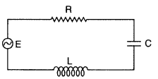
Answer: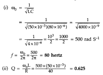
Question 24.
The figure shows a series LCR circuit connected to a variable
frequency 250 V source with L = 40 mH, C = 100 µF and R = 50 Ω.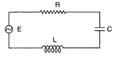
Determine :
(i) the source frequency which derives the
circuit in resonance;
(ii) The quality factor (Q) of the circuit. (Comptt.
All India 2014)
Answer:
[Hint]:
(i) 80 Hz
(ii) Q = 0.4.
Question 25.
An ideal inductor is in turn put across 220 V, 50 Hz, and 220
V, 100 Hz supplies. Will the current flowing through it in the two cases be the
same or different?
Answer:
The current through the inductor is given by l
= \(\frac{V}{X_{L}}=\frac{V}{2 \pi f L}\). The current is inversely proportional
to the frequency of applied ac.
Since the frequency is different therefore the current will also be different.
Question 26.
State the condition under which the phenomenon of resonance
occurs in a series LCR circuit, Plot a graph showing the variation of current
with a frequency of ac source in a series LCR circuit.
Answer:
The
phenomenon occurs when the inductive reactance becomes equal to the capacitive
reactance., i.e. XL – XC
⇒ ω L = \(\frac{1}{ωC}\)
⇒
ω = \(\frac{1}{\sqrt{L C}}\)
The graph is as shown below.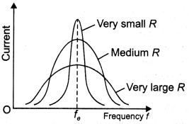
Question 27.
Give two advantages and two disadvantages of ac over dc.
Answer:
Advantages of ac:
(a) The generation and transmission of ac are
more economical than dc.
(b) The alternating voltage may be easily stepped up
or down as per need by using suitable transformers.
Disadvantages of ac:
(a) It is more fatal than dc.
(b) It cannot be
used for electrolysis.
Question 28.
In a series, LCR circuit connected to an ac source of variable
frequency and voltage v = vm sin ωt, draw a plot showing the
variation of current (l) with angular frequency (ω) for two different values of
resistance R1 and R2 (R1 > R2).
Write the condition under which the phenomenon of resonance occurs. For which
value of the resistance out of the two curves, a sharper resonance is produced?
Define the Q-factor of the circuit and give its significance. (CBSE Delhi
2013C)
Answer:
The plot is as shown.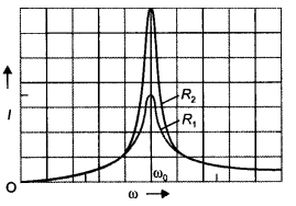
Resonance occurs in an LCR circuit when
XL = XC.
The
smaller the value of R sharper is the resonance. Therefore the curve will be
sharper for R2. It determines the sharpness of the resonance. The
larger the value of Qsharper is the resonance.
Question 29.
You are given three circuit elements X, Y, and Z. When the
element X is connected across an a.c. source of a given voltage, the current and
the voltage are in the same phase. When the element Y is connected in series
with X across the source, voltage is ahead of the current in phase by π/2. But
the current is ahead of the voltage in phase by π/2 when Z is connected in
series with X across the source. Identify the circuit elements X, Y, and Z. When
all the three elements are connected in series across the same source, determine
the impedance of the circuit. Draw a plot of the current versus the frequency of
the applied source and mention the significance of this plot. (CBSE AI 2015)
Answer:
X-Resistor, Y-Inductor, Z-Capacitor For expression of the impedance
of LCR circuit see X is a resistor
Y is a capacitor
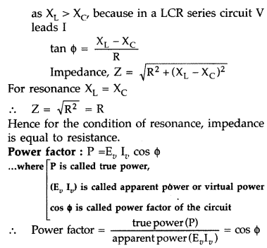
Z is an inductor
Consider the impedance triangle
Z =
\(\sqrt{R^{2}+\left(X_{t}-X_{C}\right)^{2}}\)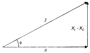
The plot is as shown.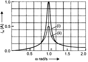
Significance, at ω = ω0 (resonance frequency) current, is
maximum.
Question 30.
Given three elements X, Y, and Z to be connected across an ac
source. With the only X connected across the ac source, voltage and current are
found to be in the same phase. With only element Y in the circuit, the voltage
lags behind the current in phase by π/2, while with the element Z in the
circuit, the voltage leads the current in phase by π/2
(a) Identify the
elements X, Y, and Z.
Answer:
X is resistor
Y is a capacitor
Z is an
inductor
Consider the impedance triangle
Z =
\(\sqrt{R^{2}+\left(X_{t}-X_{C}\right)^{2}}\)
(b) When all these elements are connected in series across the same source,
(i) determine the power factor,
Answer:
Power factor = cos Φ = R/Z
=
\(\frac{R}{\sqrt{R^{2}+\left(X_{L}-X_{c}\right)^{2}}}\)
(ii) find out the condition when the circuit is in resonant state. (CBSE AI
2019)
Answer:
Circuit will be in resonance when XL –
XC = 0
Question 31.
A coil with an air core and an electric bulb are connected in
series across a 220 V 50 Hz ac source. The bulb glows with some brightness. How
will the glow of the bulb be affected by introducing a capacitor in series with
the circuit? Justify your answer.
Answer:
The impedance of an LR circuit
is given by the expression
Z = \(\sqrt{R^{2}+X_{L}^{2}}\) and
the impedance of a series LCR circuit is given by the expression
Z =
\(\sqrt{R^{2}+\left(X_{L}-X_{C}\right)^{2}}\).
Now current flowing through the two circuits is given by V
l =
\(\frac{V}{Z}\).
Since Z decreases when a capacitor is connected to an LR circuit therefore there is an increase in current through the circuit. This increases the brightness of the bulb.
Question 32.
In the given circuit, inductor L and resistor R have
identical resistance. Two similar electric lamps B1 and B2 are connected as
shown. When switch S is closed,
(i) which one of the lamps lights
earlier,
(ii) will the lamps be equally bright after some time? Justify your
answer.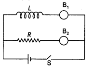
Answer:
(i) Lamp B2 connected with the resistor will light up
first. This is because the current through the inductor will grow before
attaining maximum value.
(ii) When the current through the inductor becomes
maximum, after some time, both the lamps will be equally bright.
Question 33.
Figure (a), (b), and (c) show three ac circuits in which
equal currents are flowing. If the frequency of emf be increased, how will the
current be affected in these circuits? Give the reason for your answer.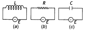
Answer:
There will be no change in the current in figure (b) as the
resistance of the resistor does not depend upon the frequency of the applied
ac.
The reactance of the inductor in figure (a) is given by XL = 2πf L. An increase in frequency increases the value of inductive reactance. This decreases the current through the circuit.
The reactance of the capacitor in figure (c) is given by XC = \(\frac{1}{\omega C}=\frac{1}{2 \pi f C}\). An increase in frequency decreases the value of capacitive reactance. This increases the current through the circuit.
Question 34.
An alternating voltage of frequency f is applied across a
series LCR circuit. Let fr be the resonance frequency for the
circuit. Will the current in the circuit lag, lead, or remain in phase with the
applied voltage when (i) f > fr (ii) f < fr Explain
your answer in each case.
Answer:
(i) When f > fr, then the
circuit behaves as an inductive circuit. Thus emf leads current. This is because
the inductive reactance is given by the expression XL = 2πfL. At
high-frequency XL will be more.
(ii) When f < fr> then the circuit behaves as a capacitive circuit. Thus emf lags current. This is because the capacitive reactance is given by the expression XC = \(\frac{1}{2 \pi f C}\). This value is more at low 2πfC frequency.
Question 35.
An inductor of unknown value, a capacitor of 100 μF and a
resistor of 10 Ω are connected in series to a 200 V. 50 Hz a.c. source. It is
found that the power factor of the circuit is unity. Calculate the inductance of
the inductor and the current amplitude. (Delhi 2008)
Answer:
As power
factor of circuit is unity :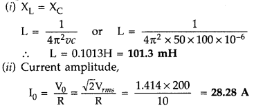
Question 36.
Two heating elements of resistances R1 and
R2 when operated at a constant supply of voltage, V, consume powers
P1 and P2 respectively. Deduce the expressions for the
power of their combination when they are, in turn, connected in
(i) series
and
(ii) parallel across the same voltage supply. (All India 2008)
Answer:
When two resistances R1 and R2 are operated at
a constant voltage supply V, their consumed power will be P1 and
P2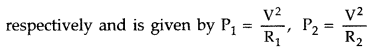
When they are connected in series, Power will be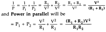
Question 37.
The figure shows a series LCR circuit with L = 5.0 H, C = 80
μF, R = 40 Ω connected to a variable frequency 240 V source. Calculate
(i)
The angular frequency of the source which drives the circuit at resonance.
(ii) The current at the resonating frequency.
(iii) The rms potential drop
across the capacitor at resonance. (Delhi 2008)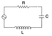
Answer: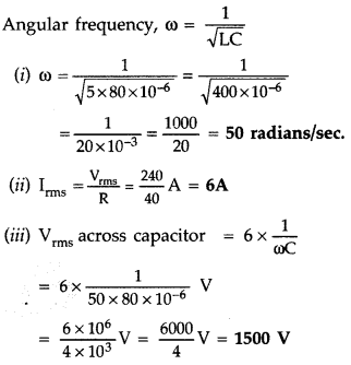
Question 38.
A series LCR circuit with L = 4.0 H,C = 100 μF and R = 60 Ω.
is connected to a variable frequency 240 V source as shown in the figure.
Calculate :
(i) the angular frequency of the source which derives the circuit
at resonance;
(ii) the current at the resonating freqency;
(iii) the rms
potential drop across the inductor at (Delhi 2008)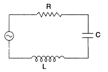
Answer: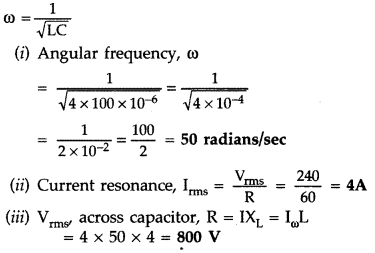
Question 39.
The figure shows a series LCR circuit with L = 10.0 H, C = 40
μF, R = 60 Ω connected to a variable frequency 240 V source.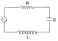
Calculate:
(i) The angular frequency of the source which
drives the circuit at resonance.
(ii) The current at the resonating
frequency.
(iii) The rms potential drop across the inductor at resonance.
(Delhi 2008)
Answer:
(i) Angular frequency, to = 50 ‘radiance/sec.
(ii) Irms = 4A
(iii) Vrms = IrmsXc = 2000 V
Question 40.
A series LCR circuit is connected to an ac source. Using the
phasor diagram, derive the expression for the impedance of the circuit. Plot a
graph to show the variation of current with frequency of the source, explaining
the nature of its variation. (All India 2008)
Answer: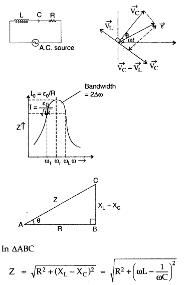
Question 41.
(a) The graphs
(i) and
(ii) shown in the figure
represent variation of opposition offered by the circuit elements, X and Y,
respectively to the flow of alternating current vs. the frequency of the applied
emf. Identify the elements X and Y.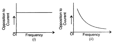
(b) Write the expression for the impedance offered by the series combination of
these two elements connected to an ac source of voltage V = V0 sin
ωt.
Show on a graph the variation of the voltage and the current with ‘out’
in the circuit. (Comptt. All India 2008)
Answer: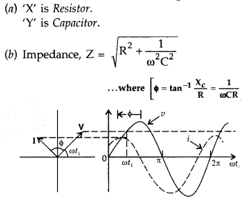
Question 42.
Draw a sketch showing the basic elements of an a.c.
generator. State its principle and explain briefly its working. (Comptt. All
India 2008)
Answer:
(a) Principle of A.C. generator : The working of an
a.c. generator is based on the principle of electromagnetic induction. When a
closed coil is rotated in a uniform magnetic field with its axis perpendicular
to the magnetic field, the magnetic flux linked with the coil changes and an
induced emf and hence a current is set up in it.
(b) Let N = number of turns in the coil
A = Area of face of each turn
B
= magnitude of the magnetic field
θ = angle which normal to the coil makes
with field B at any instant
ω = the angular velocity with which coil
rotates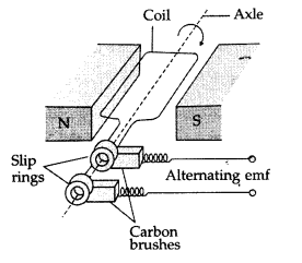
The magnetic flux linked with the coil at any instant f will
be,
ϕ = NAB cos θ = NAB cos ωt
By Faraday’s flux rule, the induced emf is
given by,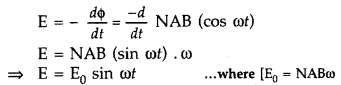
When a load of resistance R is connected across the terminals, a current I flows
in the external circuit.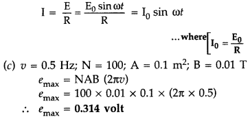
Question 43.
In a series LCR circuit connected to an ac source of variable
frequency and voltage v = Vm sin ωt, draw a plot showing the
variation of current (I) with angular frequency (ω) for two different values of
resistance R1 and R2 (R1 > R2).
Write the condition under which the phenomenon of resonance occurs. For which
value of the resistance out of the two curves, a sharper resonance is produced?
Define Q-factor of the circuit and give its significance. (Delhi 2013)
Answer:
(a) Condition for resonance to occur is XL =
XC, and Z = R.
(b) Sharper resonance is produced for
R2
(c) The Q-factor (quality factor) of series resonant circuit is
defined as the ratio of the voltage developed across the inductance of
capacitance at resonance to the impressed voltage, which is the voltage applied
across the R.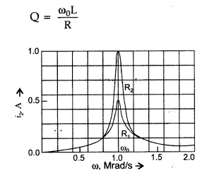
Significance : Higher the value of Q, the narrower and
sharper is the resonance and therefore circuit will be more selective
Question 44.
(i) For a given a.c., i = im sin ωt, show that the
average power dissipated in a resistor R over a complete cycle is \(\frac{1}{2}
i_{m}^{2} \mathbf{R}\).
(ii) A light bulb is rated at 100 W for a 220 V a.c.
supply. Calculate the resistance of the bulb. (All India 2013)
Answer: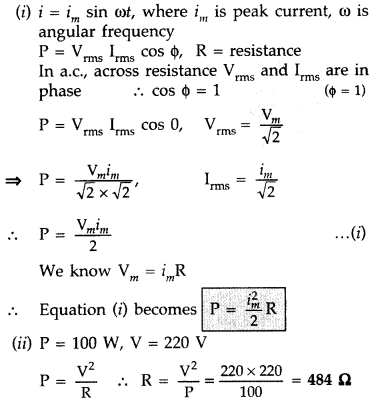
Question 45.
(a) For a given a.c., i = im sin ωt, show that the
average power dissipated in a resistor R over complete cycle is \(\frac{1}{2}
i_{m}^{2} \mathbf{R}\).
(b) A light bulb is rated at 125 W for 250 V a.c.
supply. Calculate the resistance of the bulb. (All India 2013)
Answer:
(ii) P = 125 W, V = 250 V
Where P = Power and V = Voltage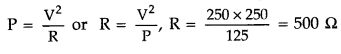
Question 46.
(a) When an a.c. source is connected to an ideal capacitor
show that the average power supplied by the source over a complete cycle is
zero.
(b) A lamp is connected in series with a capacitor. Predict your
observations when the system is connected first across a d.c. and then an a.c.
source. What happens in each case if the capacitance of the capacitor is
reduced? (Comptt. Delhi 2013)
Answer:
(a) Average power associated with a
capacitor :
When an a.c. is applied to a capacitor, the current leads the
voltage in phase by \(\frac{\pi}{2}\)radian. So we write the expressions for
instantaneous voltage and current as follows :
Work done in the circuit in small time dt will be
The average power dissipated per cycle in the capacitor is,
Thus the average power dissipated per cycle in a capacitor is zero.
(b) (i) In this case, the bulb will glow initially for a very short Bulb
duration depending upon its time constant during the charging of capacitor. Once
the capacitor is fully charged, it will not allow current to pass, hence the
bulb ceases to glow.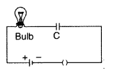
(ii) In this case, when connected to a.c. source, the bulb will glow with the
same brightness.
When the capacity of capacitor is reduced, it will have no
appreciable effect when connected to d.c. source.
However, in case when
connected to a.c. source, capacitance is reduced, hence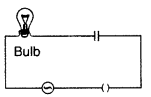
![]()
\(\chi_{\mathrm{C}}\) capactive reactance will increase and
thus the brightness of bulb will reduce.
Question 47.
A voltage V = V0 sin est is applied to a series
LCR circuit. Derive the expression for the average power dissipated over a
cycle.
Under what condition is
(i) no power dissipated even though the
current flows through the circuit,
(ii) maximum power dissipated in the
circuit? (All India 2014)
Answer:
Average power in LCR circuit :
Let
the alternating emf applied to an LCR circuit,
V = V0 sin ωt
…(i)
If alternating current developed lags behind the applied emf by a phase
angle ϕ
then, I = I0 sin(ωt – ϕ ) …(ii)
Total work done over a
complete cycle is,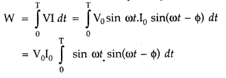
∴ Average power in LCR circuit over complete cycle is,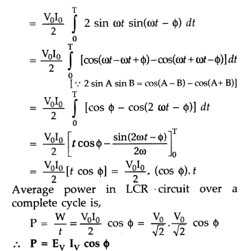
(i) No power is dissipated in purely inductive or purely capacitive circuit,
because phase difference between voltage and current is \(\frac{\pi}{2}\) and
cos ϕ = 0. It is known as wattless current.
(ii) Maximum power is dissipated in a LCR circuit at Resonance, because
XC – XL = 0 and ϕ = 0, cos ϕ = 1
Power = I2Z
= I2R
Question 48.
An inductor L of inductance XL is connected in
series with a bulb B and an ac source. How would brightness of the bulb change
when
(i) number of turns in the inductor is reduced,
(ii) an iron rod is
inserted in the inductor and
(iii) a capacitor of reactance XC =
XL is inserted in series in the circuit. Justify your Answer in each
case. (Delhi 2015)
Answer:
(i) Increases. XL = ωL
As number
of turns decrease, L decreases, hence current through the bulb increases. Also
voltage across bulb increases.
(ii) Decreases : Iron rod increases the
inductance which increases XL, hence current through the bulb
decreases./Voltage across the bulb decreases.
(iii) Increases. Under this
condition (XC = XL) the current through the bulb will
become maximum.
Question 49.
(a) Determine the value of phase difference between the
current and the voltage in the given series LCR circuit.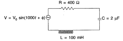
(b) Calculate the value of the additional capacitor which may be joined suitably
to the capacitor C that would make the power factor of the circuit unity. (All
India 2014)
Answer: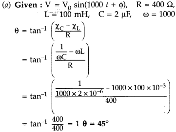
(b) Let the additional capacitor be C’ which is to be connected in parallel
with C, to increase the value of combined capacitances; hence resulting into
‘capacitive reactance’ reduced. In parallel Cnet = C + C’
When the
power factor is unity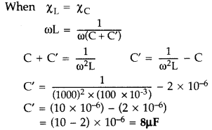
Question 50.
A circuit containing an 80 mH inductor and a 250 µF capacitor
in series connected to a 240 V, 100 rad/s supply. The resistance of the circuit
is negligible.
(i) Obtain rms value of current. ‘
(ii) What is the total
average power consumed by the circuit? (Comptt. Delhi 2014)
Answer: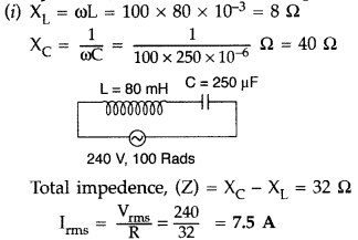
(ii) Average power consumed = 0 (Zero)
(As there is no ohmic resistance in
the current)
Question 51.
A source of ac voltage V = V0 sin cat is connected
to a series combination of a resistor ‘R’ and a capacitor ‘C’. Draw the phasor
diagram and use it to obtain the expression for
(i) impedance of the circuit
and
(ii) phase angle. (Comptt. All India 2014)
Answer:
Phasor diagram
and circuit diagram for the given circuit are,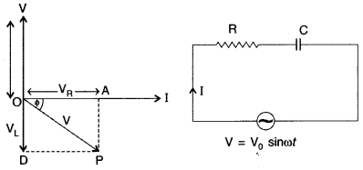
Expression for impedance and phase angle : A resistor and a capacitor are
connected in series to a source of alternating current, V = V0 sin
ωt
Let ‘I’ be the instantaneous value of current in this circuit.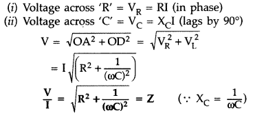
Which is the effective resistance of L – C circuit and is called its
‘impedance’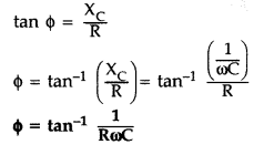
Question 52.
(i) When an AC source is connected to an ideal inductor show
that the average power supplied by the source over a complete cycle is zero.
(ii) A lamp is connected in series with an inductor and an AC source. What
happens to the brightness of the lamp when the key is plugged in and an iron rod
is inserted inside the inductor? Explain.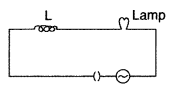
Answer: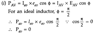
(ii) Brightness decreases because as iron rod is inserted its value of
inductance increases. Thus, current decreases and also brightness decreases.
Question 53.
Derive the expression for the average power dissipated in a
series LCR circuit for an ac source of a voltage, v = vm sin ωt,
carrying a current, i = im sin(ωt + ϕ ).
Hence define the term
“Wattless current”. State under what condition it can be realized in a circuit.
(Comptt. Delhi 2014)
Answer:
Average power in LCR circuit :
Let the
alternating emf applied to an LCR circuit,
V = V0 sin ωt …(i)
If alternating current developed lags behind the applied emf by a phase angle
ϕ
then, I = I0 sin(ωt – ϕ ) …(ii)
Total work done over a
complete cycle is,
∴ Average power in LCR circuit over complete cycle is,
(i) No power is dissipated in purely inductive or purely capacitive circuit,
because phase difference between voltage and current is \(\frac{\pi}{2}\) and
cos ϕ = 0. It is known as wattless current.
(ii) Maximum power is dissipated
in a LCR circuit at Resonance, because XC – XL = 0 and ϕ =
0, cos ϕ = 1
Power = I2Z = I2R
Question 54.
Obtain the expression for the magnetic energy stored in an
ideal inductor of self inductance L when a current I passes through it.
Hence
obtain the expression for the energy density of magnetic field B produced in the
inductor.
Answer:
Expression for Magnetic Energy density in an ideal
inductor :
Instantaneous induced emf in an inductor when current changes
through it![]()
Hence instantaneous applied voltage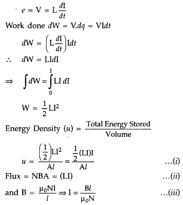
Putting the values of (LI) and (I) from equations (ii) and (iii) in equation
(i), we have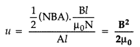
Question 55.
The current, in the LCR circuit shown in the figure is
observed to lead the voltage in phase. Without making any other change in the
circuit, a capacitor, of capacitance C0, is (appropriately) joined to
the capacitor C. This results in making the current, in the ‘modified’ circuit,
flow in phase with the applied voltage.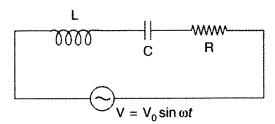
Draw a diagram of the ‘modified’ circuit and obtain an
expression for C0 in terms of ω, L and C. (Comptt. All India)
Answer:
Since the current leads the voltage in phase, hence, XC
> XL
For resonance, we must have
New value of X’C
= XL
This requires an increase in the value of C. Hence, capacitor C0
should be connected in parallel across C.
The diagram of the modified circuit
is shown. For resonance, we then have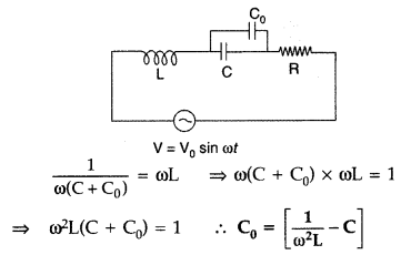
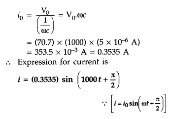
Question 56.
A 200 mH (pure) inductor, and a 5µF (pure) capacitor, are
connected, one by one, across a sinusoidal ac voltage source V = [70.7 sin (1000
t)] voltage. Obtain the expressions for the current in each case. (Comptt. All
India 2016)
Answer:
Given: For the applied voltage V = 70.7 sin(1000
t),
we have V0 = 70.7 volts, ω = 1000s-1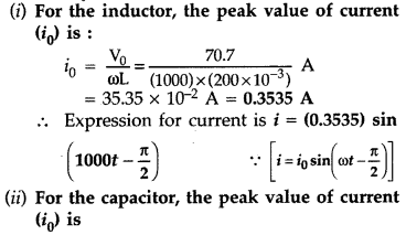
Question 57.
(i) Find the value of the phase difference between the
current and the voltage in the series LCR circuit shown here. Which one leads in
phase: current or voltage?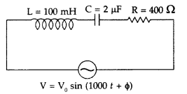
(ii) Without making any other change, find the value of the
additional capacitor Cv to be connected in parallel with the capacitor C, in
order to make the power factor of the circuit unity. (Delhi 2017)
Answer: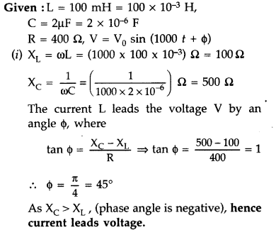
(ii) To make power factor unity, ϕ = 0°, hence we need to adjust C to a new
value C’, the condition is :
XC = XL = 100 Ω
Thus,
phase angle is 45° with the current leading the voltage.
To make power factor unity, we need to have XC also equal to 100 Ω. For this, C needs to have a value of 10µ.
We, therefore, need to put an additional capacitor of (10 – 2), i.e., 8 µF in parallel with the given capacitor.
Question 58.
For a series LCR circuit, connected to a sinusoidal ac
voltage source, identify the graph that corresponds to ω > \(\frac{1}{\sqrt{L
C}}\). Give reason.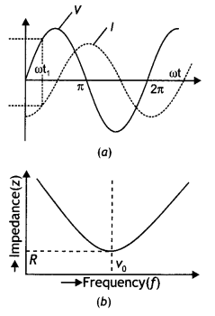
Answer:
When ω > \(\frac{1}{\sqrt{L C}}\), the circuit behaves as an
inductive circuit. In an inductive circuit, emf leads current. This is depicted
in the graph (a).
Question 59.
Draw the graphs showing the variations of (a) inductive
reactance and (b) capacitive reactance, with the frequency of applied voltage in
the ac circuit. How do the values of (a) inductive, and (b) capacitive reactance
change, when the frequency of applied voltage is tripled?
Answer:
The
graphs are as shown below.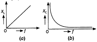
(a) The inductive reactance is given by the expression XL = 2πfL.
Therefore if the frequency is tripled then the value of XL also gets
tripled.
(b) The capacitive reactance is given by the expression
XC = \(\frac{1}{2 \pi f C}\). Therefore if the frequency is tripled
then the value of XC becomes one-third of its previous value.
Question 60.
Can the voltage drop across the inductor or the capacitor in
a series LCR circuit be greater than the applied voltage of the ac source?
Justify your answer.
Answer:
Yes, the voltage drop across the inductor or
the capacitor in a series LCR circuit be greater than the applied voltage of the
ac source. It is because the applied voltage is equal to the algebraic sum (as
obtained by the use of a phasor diagram) of VR, VL, and
VC, i.e.
V = l\(\sqrt{R^{2}+\left(X_{L}-X_{C}\right)^{2}}\)
whereas VL = l XL and VC = l
XC.
Thus, it is self-evident that VL or VC
may be greater than V.
Question 61.
Mention the factors on which the resonant frequency of a
series LCR circuit depends. Plot a graph showing the variation of the impedance
of a series LCR circuit with the frequency of the applied ac source.
Answer:
In a series LCR circuit, the resonant frequency depends on the value
of inductance L and capacitance C present in the circuit.
The graph showing
the variation of impedance Z of a series LCR circuit with the frequency f of the
applied ac source is shown below.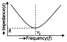
Question 19.
A lamp is connected in series with a capacitor. Predict your
observations for dc and ac connections. What happens in each case if the
capacitance of the capacitor is reduced? (NCERT)
Answer:
When a dc source
is connected to a capacitor, the capacitor gets charged and after charging no
current flows in the circuit and the lamp will not glow. There will be no change
even if C is reduced. With ac source, the capacitor offers capacitive reactance
(1/ωC), and the current flows in the circuit. Consequently, the lamp
will shine. Reducing C will increase reactance and the lamp will shine less
brightly than before.
Question 62.
A light bulb and an open coil inductor are connected to an ac
source through a key as shown in the figure.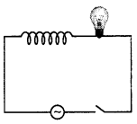
The switch is closed and after some time, an iron rod is inserted into the
interior of the inductor. The glow of the light bulb (a) increases; (b)
decreases (c) is unchanged as the iron rod is inserted. Give your answer with
reasons. (NCERT)
Answer:
As the iron rod is inserted, the magnetic field
inside the coil magnetizes the iron rod thereby increasing the magnetic field
inside it. Hence, the inductance of the coil increases. Consequently, the
inductive reactance of the coil increases. As a result, a larger fraction of the
applied ac voltage appears across the inductor, leaving less voltage across the
bulb. Therefore, the glow of the light bulb decreases.
Question 63.
Draw the effective equivalent circuit of the circuit shown in
the figure at very high frequencies and find the effective impedance. (NCERT
Exemplar)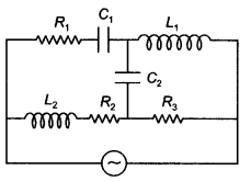
Answer:
At high frequency, the capacitive reactance is small while the
inductive reactance is large. Therefore the capacitive reactance can be
neglected while no current will flow through the inductors. Therefore the
equivalent reactance of the circuit is Z = R1 + R3 and
hence the circuit becomes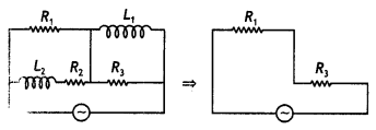
Question 64.
Study the circuits (a) and (b) shown in the figure and answer
the following questions.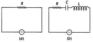
(a) Under which conditions would the rms currents in the two circuits be the
same?
Answer:
This will happen when the impedance of both the circuits is
the same, i.e. R. This is possible when circuit (b) is in resonance.
(b) Can the rms current in circuit (b) be larger than that in (a)? (NCERT
Exemplar)
Answer:
No, because in circuit (b)
lrms =
\(\frac{V_{\text {rms }}}{Z}=\frac{V_{\text {rms
}}}{\sqrt{R^{2}+\left(X_{L}-X_{C}\right)^{2}}}\), Z cannot be less than R.
Question 65.
How does the sign of the phase angle Φ, by which the supply
voltage leads the current in an LCR series circuit, change as the supply
frequency is gradually increased from very low to very high values? (NCERT
Exemplar)
Answer:
The phase angle for an LCR circuit is given by the
expression
tan Φ = \(\frac{R}{Z}=\frac{X_{L}-X_{C}}{R}=\frac{2 \pi f L-1 / 2
\pi f C}{R}\)
At low frequencies XL < XC and at high frequencies XL > XC Therefore Φ changes from negative to zero and to positive; zero at the resonant frequency.
Question 66.
A device ‘X’ is connected to an ac source. The variation of
voltage, current, and power in one complete cycle is shown in the figure.
(a)
Which curve shows power consumption over a full cycle?
(b) What is the
average power consumption over a cycle?
(c) Identify the device ‘X’. (NCERT
Exemplar)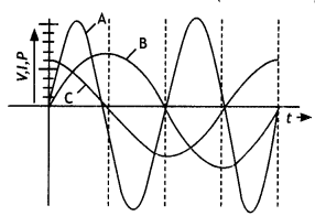
Answer:
(a) A
(b) Zero
(c) L or C or LC
Question 67.
Both alternating current and direct current are measured in
amperes. But how is the ampere defined for an alternating current? (NCERT
Exemplar)
Answer:
An ac current changes direction with the source
frequency and the charge flow would average to zero. Thus, the ac ampere must be
defined in terms of some property that is independent of the direction of the
current. Joule’s heating effect is such property and hence it is used to define
misvalue of ac.
Question 68.
A sinusoidal voltage of peak value 10 V is applied to a
series LCR circuit In which resistance, capacitance, and inductance have values
of 10 0, 1 μF, and 1 H, respectively.
Find (i) the peak voltage across the
inductor at resonance
(ii) the quality factor of the circuit. (CBSE Sample
Paper 2018-19)
Answer:
Given Vm = 10V, R = 1o Ω, L = 1 H, C = 1
μF,
VL = ?, Q = ?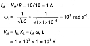
Q= ωr L/R = (103 × 1)/10 = 100
Question 69.
Draw a labeled diagram of a step-down transformer. State its
working principle Write one main cause of energy loss in this device and the
method used for reducing it.
Answer:
The labeled diagram is as
shown.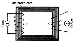
It works on the principle of mutual induction i.e., whenever magnetic flux
linked with a coil changes an emf is induced in the neighboring coil.
One main cause of loss of energy is heat produced due to the production of eddy currents. This can be reduced by laminating the iron core.
Long Answer Type
Question 1.
Prove mathematically that the average power over a complete
cycle of alternating current through an Ideal inductor is zero.
Answer:
Let the instantaneous value of voltage and current in the ac circuit containing
a pure inductor are
V = Vm sin ωt and
l = lm sin (ωt
– π/2) = – lm cos ωt
where π/2 is the phase angle by which voltage
Leads currently when ac flows through an inductor. Suppose the voltage and
current remain constant for a small-time dt. Therefore, the electrical energy
consumed in the small-time dt is
dW = V l dt
The total electrical energy consumed in one time period of ac is given
by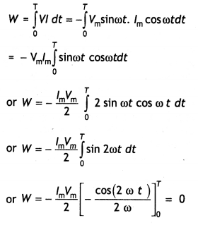
Therefore, the total electrical energy consumed in an ac circuit by a pure
inductor is W = 0
Now average power is defined as the ratio of the total electrical energy
consumed over the entire cycle to the time period of the cycle, therefore
Pav = \(\frac{W}{T}\) = 0
Hence, the average power consumed in an ac circuit by a pure inductor is
Pav = 0
Thus a pure inductor does not consume any power when ac
flows through it. Whatever energy is used in building up current is returned
back during the decay of current.
Question 2.
Draw the phasor diagram of a series LCR connected across an ac
source V= Vo sin ωt. Hence, derive the expression for the impedance
of the circuit. Obtain the conditions for the phase angle under which the
current is
(i) maximum and
(ii) minimum. (CBSE AI 2019)
Answer:
The
voltages across the various elements are drawn as shown in the figure
below.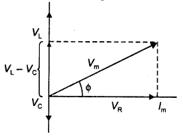
From the diagram, we observe that the vector sum of the voltage amplitudes
VR, VL, and VC equals a phasor whose length is
the maximum applied voltage Vm, where the phasor Vm makes an angle φ
with the current phasor lm. Since the voltage phasors, VL and
VC are in opposite direction, therefore, a difference phasor
(VL – VC) is drawn which is perpendicular to the phasor
VR. Adding vectorially we have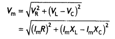
![]()
where XL = ω L and XC = 1 / ω C, therefore, we can express
the maximum current as
lm =
\(\frac{V_{\mathrm{m}}}{\sqrt{R^{2}+\left(X_{\mathrm{L}}-X_{\mathrm{C}}\right)^{2}}}\)
The impedance Z of the circuit is defined as Z = \(\sqrt{R^{2}+\left(X_{\mathrm{L}}-X_{C}\right)^{2}}\)
For maximum lm, Z should be minimum (Z = R) or XC = XL = 0 and Φ = 0
For (lm)min Φ → 90° (|XC – XL| >> R) Z → ∞
Question 3.
(a) The graphs (i) and (ii) represent the variation of the
opposition offered by the circuit element to the flow of alternating current
with a frequency of the applied emf. identify the circuit element corresponding
to each graph.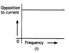
(b) Write the expression for the impedance offered by the series combinations of
the above two elements connected across the ac source. Which will be ahead in
phase in this circuit, voltage or current? (CBSE AI 2011C)
Answer:
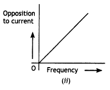
(a) In
figure (i) the opposition to the flow of current does not depend upon frequency,
the circuit element is a resistor.
In figure (ii) the opposition increases with frequency, the current element is an inductor.
(b) When the resistor R and the inductance L are connected in series across
an ac source, the impedance Z of the circuit is given by
Z =
\(\sqrt{R^{2}+X_{L}^{2}}\), where XL is the inductive reactance.
In an L – R circuit, the voltage is ahead of the current.
Question 4.
An Inductor L of inductance XL is connected in series with
bulb B and an ac source. How would the brightness of the bulb change when
(a)
the number of turns In the Inductor Is reduced,
(b) an Iron rod Is Inserted
Into the Inductor and
(c) a capacitor of reactance XC =
XL
Is Inserted in series In the circuit. Justify your answer In
each case. (CBSE Delhi 2015)
Answer:
(a) When the number of turns of the
inductor reduced it decreases the inductance of the inductor as (L ∝
n2) where n is the number of turns. This in turn decreases the
inductive reactance XL which increases the current in the circuit and
hence the brightness of the bulb decreases.
(b) When an iron rod is inserted
in the inductor, it increases the inductive reactance, which in turn decreases
the current and hence the brightness of the bulb.
(c) When XL =
XC, the circuit acts as a resistive circuit, i.e. the impedance
becomes minimum and maximum current flows. This makes the bulb glow more
brightly.
Question 5.
An inductor L of reactance XL is connected in
series with a bulb B to an ac source as shown in the figure below. Briefly
explain how the brightness of the bulb changes, when
(a) number of turns of
the inductor Is reduced? and
(b) a capacitor of reactance XC =
XL is included in series in the same circuit?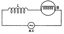
Answer:
If R is the resistance of the bulb, then the total impedance of the
circuit is Z = \(\sqrt{R^{2}+X_{L}^{2}}\) and the corresponding current is l = V
l Z.
(a) If the number of turns of the inductor is reduced then its
inductance L and consequently there is a decrease in the reactance. This leads
to a decrease in the impedance of the circuit. As a result the current flowing
through the circuit increases. This increases the brightness of the bulb.
(b) When a capacitor of reactance XC = XL is included in the circuit, then the new impedance becomes Z = \(\sqrt{R^{2}+\left(X_{L}-X_{C}\right)^{2}}\) = R. Thus the impedance has its minimum value. This increases the current through the circuit, which results in an increase in the brightness of the bulb.
Question 6.
A capacitor, ‘C’ a variable resistor ‘R’, and a bulb ‘B’ are
connected in series to the ac mains in the circuit as shown. The bulb glows with
some brightness. How will the glow of the bulb change if (a) a dielectric slab
is introduced between the plates of the capacitor, keeping resistance R to be
the same (b) the resistance R is increased keeping the same capacitance? (CBSE
Delhi 2014)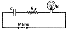
Answer:
(a) As the dielectric slab is introduced between the plates of the
capacitor, its capacitance will increase. Hence, the potential drop across the
capacitor will decrease (V = Q/C). As a result, the potential drop across the
bulb will increase (since both are connected in series). So, its brightness will
increase.
(b) As the resistance (R) is increased, the potential drop across
the resistor will increase. As a result, the potential drop across the bulb will
decrease (since both are connected in series). So, its brightness will
decrease.
Question 7.
An a.c. source generating a voltage v = vm sin ω t
is connected to a capacitor of capacitance C. Find the expression for the
current, i, flowing through it. Plot a graph of v and i versus tat to show that
the current is π/2 ahead of the voltage. A resistor of 200Ω and a capacitor of
15.0 µF are connected in series to a 220 V, 50 Hz a.c. source. Calculate the
current in the circuit and the rms voltage across the resistor and the
capacitor. Is the algebraic sum of these voltages more than the source voltage?
If yes, resolve the paradox. (All India 2008)
Answer:
(a) Voltage applied
to the capacitor, v = vm sin ωt
Let instantaneous capacitor =
v
we have, v = \(\frac{q}{C}\)![]()
According to Kirchoff’s loop rule, the voltage across the
source and the capacitor are equal at any instant of time.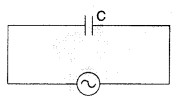
From equations (i) and (ii) we conclude that current leads
the voltage by a phase angle of π/2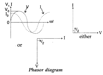
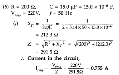
(ii) As the current is same throughout the series circuit, we have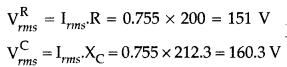
The algebraic sum of the two voltages, VR and
VC is 311.3 V which is more than the source voltage of 220 V. These
two voltages are 90° out of phase. These cannot be added like ordinary numbers.
The voltage is obtained by using Pythagoras theorem,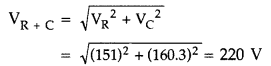
Thus if the phase difference between two voltages is properly
taken into account, the total voltage across the resistor and the capacitor is
equal to the voltage of the source.
Question 8.
Explain briefly, with the help of a labelled diagram, the
basic principle of the working of an a.c. generator.
In an a.c. generator,
coil of N turns and area A is rotated at v revolutions per second in a uniform
magnetic field B. Write the expression for the emf produced.
A 100-turn coil
of area 0.1 m2 rotates at half a revolution per second. It is placed in a
magnetic field 0.01 T perpendicular to the axis of rotation of the coil.
Calculate the maximum voltage generated in the coil. (All India 2008)
Answer:
(a) Principle of A.C. generator : The working of an a.c. generator is
based on the principle of electromagnetic induction. When a closed coil is
rotated in a uniform magnetic field with its axis perpendicular to the magnetic
field, the magnetic flux linked with the coil changes and an induced emf and
hence a current is set up in it.
(b) Let N = number of turns in the coil
A = Area of face of each turn
B
= magnitude of the magnetic field
θ = angle which normal to the coil makes
with field B at any instant
ω = the angular velocity with which coil
rotates
The magnetic flux linked with the coil at any instant f will
be,
ϕ = NAB cos θ = NAB cos ωt
By Faraday’s flux rule, the induced emf is
given by,
When a load of resistance R is connected across the terminals, a current I flows
in the external circuit.
Question 9.
(a) Derive an expression for the average power consumed in a
series LCR circuit connected to a.c. source in which the phase difference
between the voltage and the current in the circuit is 0.
(b) Define the
quality factor in an a.c. circuit. Why should the quality factor have high value
in receiving circuits? Name the factors on which it depends. (Delhi 2009)
Answer:
(a) Let an alternating current I = Im sin cot be passing
through a network of L, C and R creating a potential difference of V =
Vm sin (ωt ± ϕ ) where ϕ is the phase difference. Then the power
consumed is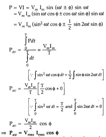
(b) Quality factor should be high to have the current corresponding to a
particular frequency to be more and to avoid the other unwanted frequencies.
Q-factor depends on f, L, R and C.
Sharpness of resonance is determined by
quality factor (Q) of the circuit i.e.,![]()
Larger the value of Q,
Sharper is the resonance i.e.
sharper peak in the current.
Question 10.
(a) Derive the relationship between the peak and the rms
value of current in an a.c. circuit.
(b) Describe briefly, with the help of a
labelled diagram, working of a step-up transformer. A step-up transformer
converts a low voltage into high voltage. Does it not violate the principle of
conservation of energy? Explain. (Delhi 2009)
Answer:
(a) R.M.S. value of
current say I = Im sin ωt is given by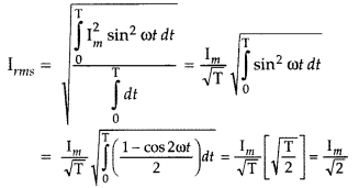
where [Im is the peak value of current]
(b) The supply of ac to the primary will bring a varying flux in the
secondary causing emf.![]()
in the secondary flux will be more than the primary as the condition
NS > NP is satisfied. Production of high voltage does
not violate the law of conservation of energy as the current will be reduced in
the process.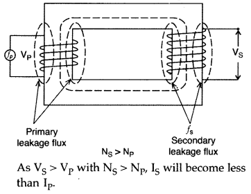
As VS > VP with NS > NP,
IS will become less than IP.
Question 11.
Describe briefly, with the help of a labelled diagram, the
basic elements of an a.c. generator. State its underlying principle. Show
diagrammatically how an alternating emf is generated by a loop of wire rotating
in a magnetic field. Write the expression for the instantaneous value of the emf
induced in the rotating loop. (Delhi 2010)
Answer:
(a) Principle of A.C.
generator : The working of an a.c. generator is based on the principle of
electromagnetic induction. When a closed coil is rotated in a uniform magnetic
field with its axis perpendicular to the magnetic field, the magnetic flux
linked with the coil changes and an induced emf and hence a current is set up in
it.
(b) Let N = number of turns in the coil
A = Area of face of each turn
B
= magnitude of the magnetic field
θ = angle which normal to the coil makes
with field B at any instant
ω = the angular velocity with which coil
rotates
The magnetic flux linked with the coil at any instant f will
be,
ϕ = NAB cos θ = NAB cos ωt
By Faraday’s flux rule, the induced emf is
given by,
When a load of resistance R is connected across the terminals, a current I flows
in the external circuit.
Diagram of how an alternating emf is generated by a loop of wire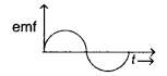
Question 12.
A series LCR circuit is connected to an a.c. source having
voltage v = vm sin ωt.
Derive the expression for the instantaneous
current I and its phase relationship to the applied voltage.
Obtain the
condition for resonance to occur. Define ‘power factor’. State the conditions
under which it is
(i) maximum and
(ii) minimum. (Delhi 2010)
Answer:
(a) Suppose a resistance R, an inductance L and capacitance C are
connected in series to a source of alternating emf ε given by
ε =
ε0 sin ωt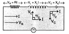
Let I be the instantaneous value of current in the series
circuit. Then voltage across the three components are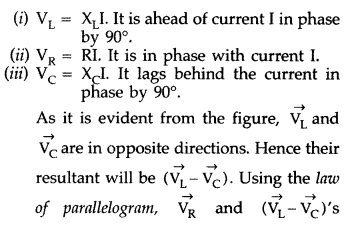
resultant is equal to the applied emf \(\vec{\varepsilon}\), as given by the
diagonal of the parallelogram.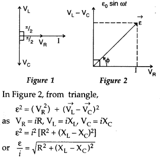
Clearly \(\frac{\varepsilon}{i}\) is the effective resistance of the series LCR
circuit and is called its impedance (Z)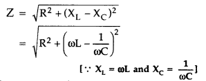
When XL = XC, the voltage and current
are in the same phase. In such a situation, the circuit is known as
non-inductive circuit.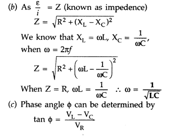
(i) Power factor is maximum when the circuit contains only resistance R. In that
case ϕ = 0, cos ϕ = 1.
(ii) Power factor is minimum when the circuit contains
purely capacitive or inductive circuit. In this case cos ϕ = 0 and no power is
dissipated even though a current is flowing in the circuit.
Question 13.
Draw a schematic diagram of a step-up transformer. Explain
its working principle. Deduce the expression for the secondary to primary
voltage in terms of the number of turns in the two coils. In an ideal
transformer, how is this ratio related to the currents in the two coils? How is
the transformer used in large scale transmission and distribution of electrical
energy over long distances? (All India 2010)
Answer:
A transformer is an
electrical device for converting an alternating current at low voltages into
that at high voltage or vice versa.
If it increases the input voltage, it is
called step- up-transformer.
Principle : It works on the principle of mutual induction
i.e., “when a changing current is passed through one of the two inductively
coupled coils, an induced emf is set up in the other coil.”
Working : As the alternating current flows through the primary, it generates
an alternating magnetic flux in the core which also passes through the
secondary. This changing flux sets up an induced emf in the secondary, also a
self- induced emf in the primary. If there is no leakage of magnetic flux, then
flux linked with each turn of the primary will be equal to that linked with each
turn of the secondary.![]()
…where
[Np and Ns are number of turns in the primary and
secondary respectively,
Vp and Vs are their respective
voltages]
This ratio \(\frac{\mathrm{N}_{\mathrm{S}}}{\mathrm{N}_{\mathrm{P}}}\) is called
the turns ratio.
Assuming the transformer to be ideal one, so that there are
no energy losses, then
Input power = output power
Vplp = VSIS
…where [IP
and IS are the current in the primary and secondary
respectively
In a step up transformer, Ns > Np i.e., the turns
ratio is greater than 1 and therefore Vs > Vp.
The
output voltage is greater than the input voltage.
Main assumptions :
- The primary resistance and current are small.
- The same flux links both with the primary and secondary windings as the flux leakage from due core is negligible (small).
- The terminals of the secondary are open or the current taken from it, is small, (any two)
For long distance transmission, the voltage output of the generator is stepped-up (so that current is reduced and consequently, IR loss is reduced). It is transmitted over long distance and is stepped- down at distributing substations at consumers’ end.
Question 13 a.
(i) With the help of a labelled diagram, describe briefly the
underlying principle and working of a step-up transformer.
(ii) Write any two
sources of energy loss in a transformer.
(iii) A step up transformer converts
a low input voltage into a high output voltage. Does it violate law of
conservation of energy? Explain. (Delhi 2011)
Answer:
(i) A transformer is
an electrical device for converting an alternating current at low voltages into
that at high voltage or vice versa.
If it increases the input voltage, it is
called step- up-transformer.
Principle : It works on the principle of mutual induction
i.e., “when a changing current is passed through one of the two inductively
coupled coils, an induced emf is set up in the other coil.”
Working : As the alternating current flows through the primary, it generates
an alternating magnetic flux in the core which also passes through the
secondary. This changing flux sets up an induced emf in the secondary, also a
self- induced emf in the primary. If there is no leakage of magnetic flux, then
flux linked with each turn of the primary will be equal to that linked with each
turn of the secondary.![]()
…where
[Np and Ns are number of turns in the primary and
secondary respectively,
Vp and Vs are their respective
voltages]
This ratio \(\frac{\mathrm{N}_{\mathrm{S}}}{\mathrm{N}_{\mathrm{P}}}\) is called
the turns ratio.
Assuming the transformer to be ideal one, so that there are
no energy losses, then
Input power = output power
Vplp = VSIS
…where [IP
and IS are the current in the primary and secondary
respectively
In a step up transformer, Ns > Np i.e., the turns
ratio is greater than 1 and therefore Vs > Vp.
The
output voltage is greater than the input voltage.
Main assumptions :
- The primary resistance and current are small.
- The same flux links both with the primary and secondary windings as the flux leakage from due core is negligible (small).
- The terminals of the secondary are open or the current taken from it, is small, (any two)
For long distance transmission, the voltage output of the generator is stepped-up (so that current is reduced and consequently, IR loss is reduced). It is transmitted over long distance and is stepped- down at distributing substations at consumers’ end.
(ii) Two sources of energy loss in a transformer:
1. Copper loss”: Some
energy is lost due to heating of copper wires used in the primary and secondary
windings. This power loss (= I2R) can be minimised by using thick
copper wires of low resistance.
2. Eddy current loss : The alternating magnetic flux induces eddy currents in the iron core which leads to some energy loss in the form of heat. This loss can be reduced by using laminated iron core.
(iii) No, a step up transformer does not violate law of conservation of energy because whatever is gained in voltage ratio is lost in the current ratio and vice-versa. It steps up the voltage while it steps down the current.
Question 14.
Derive an expression for the impedance of a series LCR
circuit connected to an AC supply of variable frequency.
Plot a graph showing
variation of current with the frequency of the applied voltage.
Explain
briefly how the phenomenon of resonance in the circuit can be used in the tuning
mechanism of a radio or a TV set. (Delhi 2011)
Answer:
Expression for
impedance:
(a) Let an alternating current I = Im sin cot be
passing through a network of L, C and R creating a potential difference of V =
Vm sin (ωt ± ϕ ) where ϕ is the phase difference. Then the power
consumed is
(b) Quality factor should be high to have the current corresponding to a
particular frequency to be more and to avoid the other unwanted frequencies.
Q-factor depends on f, L, R and C.
Sharpness of resonance is determined by
quality factor (Q) of the circuit i.e.,![]()
Larger the value of Q,
Sharper is the resonance i.e.
sharper peak in the current.
Resonant circuit can be used in the tuning
mechanism of a radio or a TV set.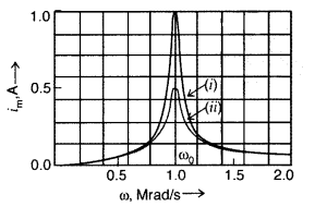
The antenna of a radio accepts signals from many broadcasting
stations. The signals picked up in the antenna acts as a source in the tuning
circuit of the radio, so the circuit can be driven at many frequencies. But to
hear one particular radio station, we tune the radio. In tuning, we vary the
capacitance of a capacitor in the tuning circuit such that the resonant
frequency of the circuit becomes nearly equal to the frequency of the radio
signal received. When this happens, the amplitude of the current with the
frequency of the signal of the . particular radio station in the circuit is
maximum.
Question 15.
State the working of a.c. generator with the help of a
labelled diagram.
The coil of an a.c. generator having N turns, each of area
A, is rotated with a constant angular velocity to. Deduce the expression for the
alternating emf generated in the coil.
What is the source of energy
generation in this device? (All India 2011)
Answer:
AC generator: A dynamo
or generator is a device which converts mechanical energy into electrical
energy. It is based on the principal of electromagnetic energy into electrical
energy. It is based on the principle of electromagnetic induction.
Construction : It consists of the four main parts :
(i) Field Magnet : It
produces the magnetic field. In the case of a low power dynamo, the magnetic
field is generated by a permanent magnet, while in the case of large power
dynamo, the magnetic field is produced by an electromagnet. ;
(ii) Armature : It consists of a large number of turns of insulated wire in the soft iron drum or ring. It can revolve round an axle between the two poles of the field magnet. The drum or ring serves the two purposes :
- It serves as support to coils and
- It increases the magnetic field due to air core being replaced by an iron core.
(iii) Slip Rings : The slip rings R1 and R2 are the two metal rings to which the ends of armature coil are connected. These rings are fixed to the shaft which rotates the armature coil so that the rings also rotate along with the armature.
(iv) Brushes : These are two flexible metal plates or carbon rods
(B1 and B2) which are fixed and constantly touch the
revolving rings. The output current in external load RL is taken through these
brushes.
Working : When the armature coil is rotated in the strong magnetic
field, the magnetic flux linked with the coil changes and the current is induced
in the coil, its direction being given by Fleming’s right hand rule. Considering
the armature to be in vertical position and as it rotates in anticlockwise
direction, the wire ab moves upward and cd downward, so that the direction of
induced current is shown in fig. In the external circuit, the current flows
along B1RLB2. The direction of current remains
unchanged during the first half turn of armature. During the second half
revolution, the wire ab moves downward and cd upward, so the direction of
current is reversed and in external circuit it flows along
B2RLB1. Thus the direction of induced emf and
current changes in the external circuit after each half revolution.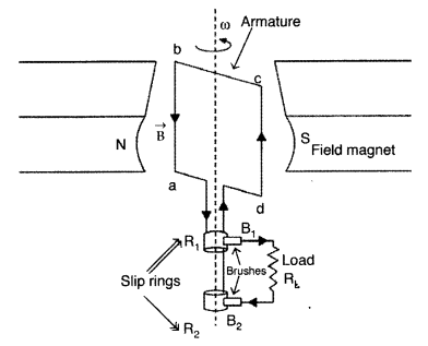
Numerical :
N = number of turns in the coil
A = area enclosed by each
turn of coil
\(\overrightarrow{\mathrm{B}}\) = strength of magnetic
field
θ = angle, which is normal to the coil, makes with
\(\overrightarrow{\mathrm{B}}\) at any instant t
∴ Magnetic flux linked with
the coil in this position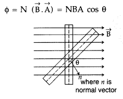
If the coil rotates with an angular velocity ω and turns
through an angle θ in time t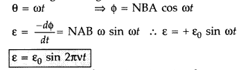
Source of energy : This induced emf is the source of energy generations in this
device.
Question 16.
(a) A voltage V = V0 sin ωt applied to a series
LCR circuit drives a current i = i0 sin ωt in the circuit. Deduce the
expression for the average power dissipated in the circuit.
(b) For circuits
used for transporting electric power, a low power factor implies large power
loss in transmission. Explain.
(c) Define the term ‘wattless current’.
(Comptt. Delhi 2012)
Answer: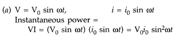
If the instantaneous power remains constant for a small time dt
then small
amount of work done in maintaining the current for a small time dt is,
dW =
V0i0 sin2 ωtdt
Total work done or energy
spent in maintaining current over one full cycle,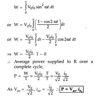
(b) A transformer is an electrical device for converting an alternating current
at low voltages into that at high voltage or vice versa.
If it increases the
input voltage, it is called step- up-transformer.
Principle : It works on the principle of mutual induction
i.e., “when a changing current is passed through one of the two inductively
coupled coils, an induced emf is set up in the other coil.”
Working : As the alternating current flows through the primary, it generates
an alternating magnetic flux in the core which also passes through the
secondary. This changing flux sets up an induced emf in the secondary, also a
self- induced emf in the primary. If there is no leakage of magnetic flux, then
flux linked with each turn of the primary will be equal to that linked with each
turn of the secondary.![]()
…where
[Np and Ns are number of turns in the primary and
secondary respectively,
Vp and Vs are their respective
voltages]
This ratio \(\frac{\mathrm{N}_{\mathrm{S}}}{\mathrm{N}_{\mathrm{P}}}\) is called
the turns ratio.
Assuming the transformer to be ideal one, so that there are
no energy losses, then
Input power = output power
Vplp = VSIS
…where [IP
and IS are the current in the primary and secondary
respectively
In a step up transformer, Ns > Np i.e., the turns
ratio is greater than 1 and therefore Vs > Vp.
The
output voltage is greater than the input voltage.
Main assumptions :
- The primary resistance and current are small.
- The same flux links both with the primary and secondary windings as the flux leakage from due core is negligible (small).
- The terminals of the secondary are open or the current taken from it, is small, (any two)
For long distance transmission, the voltage output of the generator is stepped-up (so that current is_ reduced and consequently, IR loss is reduced). It is transmitted over long distance and is stepped- down at distributing substations at consumers’ end.
(c) Wattless current. The current which consumes no power for its maintenance in the circuit is called wattless current or idle current.
Question 17.
(a) An ac source of voltage v = v0 sin ωt is
connected across a series combination of an inductor, a capacitor and a
resistor. Use the phasor diagram to obtain the expression for
(i) impedance
of the circuit and
(ii) phase angle between the voltage and the current.
(b) A capacitor of unknown capacitance, a resistor of 100 Ω and an inductor of
self-inductance L = (4/π2) henry are in series connected to an ac
source of 200 V and 50 Hz. Calculate the value of the capacitance and the
current that flows in the circuit when the current is in phase with the voltage.
(Comptt. All India 2012)
Answer:
(a) (i) Impedance of circuit : The
effective resistance offered by a series LCR circuit is called its
impedance.
Suppose an inductance L, capacitance C and resistance R are
connected in series to a source of alternating emf, V = V0 sin
ωt.
Let I be the instantaneous value of current in the series circuit.
Then voltages across the three components are : ‘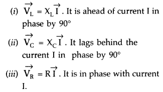
These
voltages are shown in the phasor in Figure 2.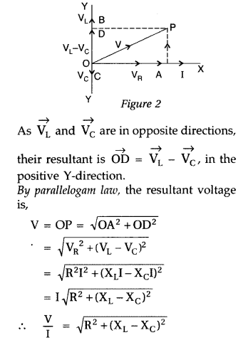
Clearly V/I is the effective resistance of the series LCR circuit and is called
its impedance (Z).![]()
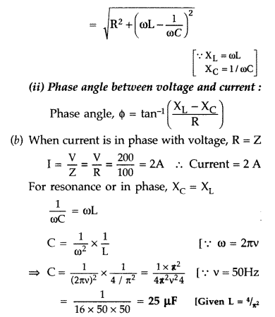
Question 18.
(a) Explain with the help of a labelled diagram, the
principle and working of a transformer. Deduce the expression for its working
formula.
(b) Name any four causes of energy loss in an actual transformer.
(Comptt. All India 2012)
Answer:
(a) Principle. It is a device which
converts high voltage a.c. into low voltage a.c. and vice versa. It is based
upon the principle of mutual induction. When alternating current passes through
a coil, an induced emf is set up in the neighbouring coil.
Construction. A
transformer consists of two coils of many turns of insulated copper wire wound
on a closed laminated iron core. One of the coils known as Primary ‘P’ is
connected to A.C. supply. The other coil known as Secondary ‘S’ is connected to
the load. Working. When an alternating current passes through the primary, the
magnetic flux through the iron core changes which does two things. It produces
emf in the primary and an induced emf is also set up in the secondary. If we
assume that the resistance of primary is negligible, the back emf will be equal
to the voltage applied to the primary.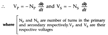
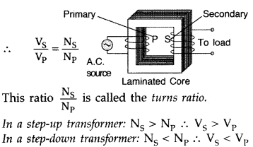
(b) Four causes of energy loss :
- Magnetic flux loss
- Hystersis loss
- Iron loss
- Losses due to the resistance of primary and secondary coils.
Question 19.
(a) Draw a schematic sketch of an ac generator describing its
basic elements. State briefly its working principle. Show a plot of variation
of
(i) Magnetic flux and
(ii) Alternating emf versus time generated by a
loop of wire rotating in a magnetic field.
(b) Why is choke coil needed in
the use of fluorescent tubes with ac mains? (Delhi 2014)
Answer:
(a) AC
generator.
(a) Principle of A.C. generator : The working of an a.c. generator
is based on the principle of electromagnetic induction. When a closed coil is
rotated in a uniform magnetic field with its axis perpendicular to the magnetic
field, the magnetic flux linked with the coil changes and an induced emf and
hence a current is set up in it.
(b) Let N = number of turns in the coil
A
= Area of face of each turn
B = magnitude of the magnetic field
θ = angle
which normal to the coil makes with field B at any instant
ω = the angular
velocity with which coil rotates
The magnetic flux linked with the coil at any instant f will
be,
ϕ = NAB cos θ = NAB cos ωt
By Faraday’s flux rule, the induced emf is
given by,
When a load of resistance R is connected across the terminals, a current I flows
in the external circuit.
(i) Graph between magnetic flux and time, according to equation (i), shown below in Graph (i)
(ii) As the coil rotates, angle θ changes. Therefore, magnetic flux ϕ linked
with the coil changes and an emf is induced in the coil. At this instant f, if e
is the emf , induced in the coil, then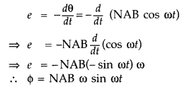
(iii) The graph between alternating emf ‘ versus time is shown below in Graph
(ii).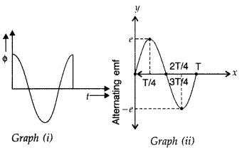
(b) A choke coil is an electrical appliance used for controlling current in a
a.c. circuit. Therefore, if we use a resistance R for the same purpose, a lot of
energy would be wasted in the form of heat etc.
Question 20.
(a) A series LCR circuit is connected to an a.c. source of
variable frequency. Draw a suitable phasor diagram to deduce the expressions for
the amplitude of the current and phase angle.
(b) Obtain the condition at
resonance. Draw a plot showing the variation of current with the frequency of
a.c. source for two resistances R1 and (R1 >
R2). Hence define the quality factor, Q and write its role in the
tuning of the circuit. (Comptt. Delhi 2014)
Answer:
(a) Suppose a
resistance R, an inductance L and capacitance C are connected in series to a
source of alternating emf ε given by
ε = ε0 sin ωt
Let I be the instantaneous value of current in the series
circuit. Then voltage across the three components are
resultant is equal to the applied emf \(\vec{\varepsilon}\), as given by the
diagonal of the parallelogram.
Clearly \(\frac{\varepsilon}{i}\) is the effective resistance of the series LCR
circuit and is called its impedance (Z)
When XL = XC, the voltage and current
are in the same phase. In such a situation, the circuit is known as
non-inductive circuit.
(i) Power factor is maximum when the circuit contains only resistance R. In that
case ϕ = 0, cos ϕ = 1.
(ii) Power factor is minimum when the circuit contains
purely capacitive or inductive circuit. In this case cos ϕ = 0 and no power is
dissipated even though a current is flowing in the circuit.
(b)
(a)
Condition for resonance to occur is XL = Xc, and Z =
R.
(b) Sharper resonance is produced for Rr
(c) The Q-factor (quality
factor) of series resonant circuit is defined as the ratio of the voltage
developed across the inductance of capacitance at resonance to the impressed
voltage, which is the voltage applied across the R.
Significance : Higher the value of Q, the narrower and
sharper is the resonance and therefore circuit will be more selective
Question 21.
(a) Draw a labelled diagram of a.c. generator and state its
working principle.
(b) How is magnetic flux linked with the armature coil
changed in a generator?
(c) Derive the expression for maximum value of the
induced emf and state the rule that gives the direction of the induced emf.
(d) Show the variation of the emf generated
versus time as the armature is
rotated with respect to the direction of the magnetic field. (Comptt. Delhi
2014)
Answer:
(a) Principle of A.C. generator : The working of an a.c.
generator is based on the principle of electromagnetic induction. When a closed
coil is rotated in a uniform magnetic field with its axis perpendicular to the
magnetic field, the magnetic flux linked with the coil changes and an induced
emf and hence a current is set up in it.
(b) Let N = number of turns in the coil
A = Area of face of each turn
B
= magnitude of the magnetic field
θ = angle which normal to the coil makes
with field B at any instant
ω = the angular velocity with which coil
rotates
The magnetic flux linked with the coil at any instant f will
be,
ϕ = NAB cos θ = NAB cos ωt
By Faraday’s flux rule, the induced emf is
given by,
When a load of resistance R is connected across the terminals, a current I flows
in the external circuit.
(c) Direction of induced emf can be determined by using Fleming’s Left hand
rule.
(d)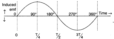
Question 22.
(a) Draw a schematic arrangement for winding of primary and
secondary coil in a transformer when the two coils are wound on top of each
other.
(b) State the underlying principle of a transformer and obtain the
expression for the ratio of secondary to primary voltage in terms of the
(i)
number of secondary and primary windings and
(ii) primary and secondary
currents.
(c) Write the main assumption involved in deriving the above
relations.
(d) Write any two reasons due to which energy losses may occur in
actual transformers. (Comptt. All India 2014)
Answer:
A transformer is an
electrical device for converting an alternating current at low voltages into
that at high voltage or vice versa.
If it increases the input voltage, it is
called step- up-transformer.
Principle : It works on the principle of mutual induction
i.e., “when a changing current is passed through one of the two inductively
coupled coils, an induced emf is set up in the other coil.”
Working : As the alternating current flows through the primary, it generates
an alternating magnetic flux in the core which also passes through the
secondary. This changing flux sets up an induced emf in the secondary, also a
self- induced emf in the primary. If there is no leakage of magnetic flux, then
flux linked with each turn of the primary will be equal to that linked with each
turn of the secondary.![]()
…where
[Np and Ns are number of turns in the primary and
secondary respectively,
Vp and Vs are their respective
voltages]
This ratio \(\frac{\mathrm{N}_{\mathrm{S}}}{\mathrm{N}_{\mathrm{P}}}\) is called
the turns ratio.
Assuming the transformer to be ideal one, so that there are
no energy losses, then
Input power = output power
Vplp = VSIS
…where [IP
and IS are the current in the primary and secondary
respectively
In a step up transformer, Ns > Np i.e., the turns
ratio is greater than 1 and therefore Vs > Vp.
The
output voltage is greater than the input voltage.
Main assumptions :
- The primary resistance and current are small.
- The same flux links both with the primary and secondary windings as the flux leakage from due core is negligible (small).
- The terminals of the secondary are open or the current taken from it, is small, (any two)
For long distance transmission, the voltage output of the generator is stepped-up (so that current is_ reduced and consequently, IR loss is reduced). It is transmitted over long distance and is stepped- down at distributing substations at consumers’ end.
(d) Reasons due to which energy losses may occur :
- Flux leakage
- Losses due to the resistance of primary and secondary coils
- eddy currents
- hystersis
Question 23.
(i) An a.c. source of voltage V = V0 sin ωt is
connected to a series combination of L, C and R. Use the phasor diagram to
obtain expressions for impedance of the circuit and phase angle between voltage
and current. Find the condition when current will be in phase with the voltage.
What is the circuit in this condition called?
(ii) In a series LR circuit
XL = R and power factor of the circuit is P1. When
capacitor with capacitance C such that XL = XC is put in
series, the power factor becomes P2. Calculate
P1/P2.
Answer:
(a) (i) Impedance of circuit : The
effective resistance offered by a series LCR circuit is called its
impedance.
Suppose an inductance L, capacitance C and resistance R are
connected in series to a source of alternating emf, V = V0 sin
ωt.
Let I be the instantaneous value of current in the series circuit.
Then voltages across the three components are : ‘
These
voltages are shown in the phasor in Figure 2.
Clearly V/I is the effective resistance of the series LCR circuit and is called
its impedance (Z).![]()
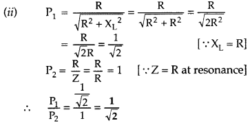
Question 24.
(i) Write the function of a transformer. State its principle
of working with the help of a diagram. Mention various energy losses in this
device.
(ii) The primary coil of an ideal step up transformer has 100 turns
and transformation ratio is also 100. The input voltage and power are
respectively 220 V and 1100 W. Calculate
(a) number of turns in secondary
(b) current in primary
(c) voltage across secondary
(d) current in
secondary
(e) power in secondary (Delhi 2016)
Answer:
(i) (a)
Principle. It is a device which converts high voltage a.c. into low voltage a.c.
and vice versa. It is based upon the principle of mutual induction. When
alternating current passes through a coil, an induced emf is set up in the
neighbouring coil.
Construction. A transformer consists of two coils of many turns of insulated
copper wire wound on a closed laminated iron core. One of the coils known as
Primary ‘P’ is connected to A.C. supply. The other coil known as Secondary ‘S’
is connected to the load. Working. When an alternating current passes through
the primary, the magnetic flux through the iron core changes which does two
things. It produces emf in the primary and an induced emf is also set up in the
secondary. If we assume that the resistance of primary is negligible, the back
emf will be equal to the voltage applied to the primary.
(b) Four causes of energy loss :
- Magnetic flux loss
- Hystersis loss
- Iron loss
- Losses due to the resistance of primary and secondary coils.
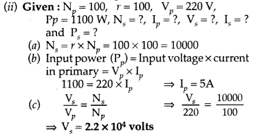
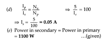
Question 25.
(i) Draw a labelled diagram of a step-down transformer. State
the priciple of its working.
(ii) Express the turn ratio in terms of
voltages.
(iii) Find the ratio of primary and secondary currents in terms of
turn ratio in an ideal transformer
(iv) How much current is drawn by the
primary of a transformer connected to 220 V supply when it delivers power to a
110V – 550 W refrigerator? (All India 2016)
Answer: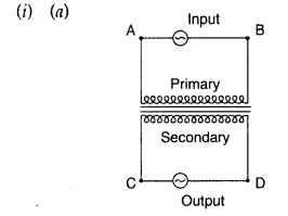
Labelled diagram of a step-down transformer :
(b) Mutual Induction, which means “whenever an alternative voltage is applied
in the primary windings /coil, an emf is induced in the secondary windings
(Coil).”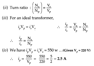
Question 26.
Discuss how Faraday’s law of e.m. induction is applied in an
ac-generator for converting mechanical energy into electrical energy.
Obtain
an expression for the instantaneous value of the induced emf in an ac generator.
Draw graphs to show the ‘phase relationship’ between the instantaneous
(i)
magnetic flux (ϕ) linked with the coil and
(ii) induced emf (ε) in the coil.
‘ (Comptt. Delhi 2016)
Answer:
Faradays law of e.m. induction and
expression for instantaneous value of induced emf
(a) Principle of A.C.
generator : The working of an a.c. generator is based on the principle of
electromagnetic induction. When a closed coil is rotated in a uniform magnetic
field with its axis perpendicular to the magnetic field, the magnetic flux
linked with the coil changes and an induced emf and hence a current is set up in
it.
(b) Let N = number of turns in the coil
A = Area of face of each turn
B
= magnitude of the magnetic field
θ = angle which normal to the coil makes
with field B at any instant
ω = the angular velocity with which coil
rotates
The magnetic flux linked with the coil at any instant f will
be,
ϕ = NAB cos θ = NAB cos ωt
By Faraday’s flux rule, the induced emf is
given by,
When a load of resistance R is connected across the terminals, a current I flows
in the external circuit.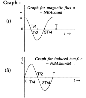
Question 27.
Draw an arrangement for winding of primary and secondary
coils in a transformer with two coils on a separate limb of the core.
State
the underlying principle of a transformer. Deduce the expression for the ratio
of secondary voltage to the primary voltage in terms of the ratio of the number
of turns of primary and secondary winding. For an ideal transformer, obtain the
ratio of primary and secondary currents in terms of the ratio of the voltages in
the secondary and primary voltages.
Write any two reasons for the energy
losses which occur in actual transformers. (Comptt. Delhi 2016)
Answer:
(a) Principle. It is a device which converts high voltage a.c. into low voltage
a.c. and vice versa. It is based upon the principle of mutual induction. When
alternating current passes through a coil, an induced emf is set up in the
neighbouring coil.
Construction. A transformer consists of two coils of many turns of insulated
copper wire wound on a closed laminated iron core. One of the coils known as
Primary ‘P’ is connected to A.C. supply. The other coil known as Secondary ‘S’
is connected to the load. Working. When an alternating current passes through
the primary, the magnetic flux through the iron core changes which does two
things. It produces emf in the primary and an induced emf is also set up in the
secondary. If we assume that the resistance of primary is negligible, the back
emf will be equal to the voltage applied to the primary.
(b) Four causes of energy loss :
- Magnetic flux loss
- Hystersis loss
- Iron loss
- Losses due to the resistance of primary and secondary coils.
Question 28.
(a) Draw a labelled diagram of AC generator. Derive the
expression for the instantaneous value of the emf induced in the coil.
(b) A
circular coil of cross-sectional area 200 cm2 and 20 turns is rotated
about the vertical diameter with angular speed of 50 rad s-1 in a
uniform magnetic field of magnitude 3.0 × 10⁻² T. Calculate the
maximum value of the current in the coil. (Delhi 2017)
Answer:
(a)
Principle of A.C. generator : The working of an a.c. generator is based on the
principle of electromagnetic induction. When a closed coil is rotated in a
uniform magnetic field with its axis perpendicular to the magnetic field, the
magnetic flux linked with the coil changes and an induced emf and hence a
current is set up in it.
(b) Let N = number of turns in the coil
A = Area of face of each turn
B
= magnitude of the magnetic field
θ = angle which normal to the coil makes
with field B at any instant
ω = the angular velocity with which coil
rotates
The magnetic flux linked with the coil at any instant f will
be,
ϕ = NAB cos θ = NAB cos ωt
By Faraday’s flux rule, the induced emf is
given by,
When a load of resistance R is connected across the terminals, a current I flows
in the external circuit.
(b) Given : A = 200 cm2 = 200 × 10-4 m2
N =
20 turns, ω = 50 rad s-1,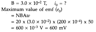
Maximum value of i0 = mA
[ ∵ Numerical value of R is not
given]
Question 29.
(a) Draw a labelled diagram of a step-up transformer. Obtain
the ratio of secondary to primary voltage in terms of number of turns and
currents in the two coils.
(b) A power transmission line feeds input power at
2200 V to a step-down transformer with its primary windings having 3000 turns.
Find the number of turns in the secondary to get the power output at 220 V.
(Delhi 2017)
Answer:
(a) A transformer is an electrical device for
converting an alternating current at low voltages into that at high voltage or
vice versa.
If it increases the input voltage, it is called step-
up-transformer.
Principle : It works on the principle of mutual induction
i.e., “when a changing current is passed through one of the two inductively
coupled coils, an induced emf is set up in the other coil.”
Working : As the alternating current flows through the primary, it generates
an alternating magnetic flux in the core which also passes through the
secondary. This changing flux sets up an induced emf in the secondary, also a
self- induced emf in the primary. If there is no leakage of magnetic flux, then
flux linked with each turn of the primary will be equal to that linked with each
turn of the secondary.![]()
…where
[Np and Ns are number of turns in the primary and
secondary respectively,
Vp and Vs are their respective
voltages]
This ratio \(\frac{\mathrm{N}_{\mathrm{S}}}{\mathrm{N}_{\mathrm{P}}}\) is called
the turns ratio.
Assuming the transformer to be ideal one, so that there are
no energy losses, then
Input power = output power
Vplp = VSIS
…where [IP
and IS are the current in the primary and secondary
respectively
In a step up transformer, Ns > Np i.e., the turns
ratio is greater than 1 and therefore Vs > Vp.
The
output voltage is greater than the input voltage.
Main assumptions :
- The primary resistance and current are small.
- The same flux links both with the primary and secondary windings as the flux leakage from due core is negligible (small).
- The terminals of the secondary are open or the current taken from it, is small, (any two)
For long distance transmission, the voltage output of the generator is stepped-up (so that current is reduced and consequently, IR loss is reduced). It is transmitted over long distance and is stepped- down at distributing substations at consumers’ end.
(b) Given : Vp = 2200 V, Np = 3000 turns,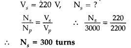
Question 30.
A device ‘X’ is connected to an ac source V = V0 sin cot. The
variation of voltage, current and power in one cycle is shown in the following
graph:
(a) Identify the device ‘X’.
(b) Which of the curves A, B and C
represent the voltage, current and the power consumed in the circuit? Justify
your
answer.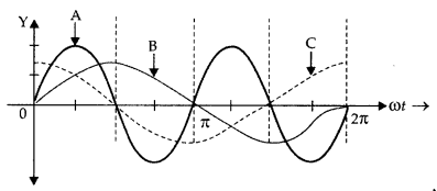
(c) How does it impedance vary with frequency of the ac source ? Show
graphically.
(d) Obtain an expression for the current in the circuit and its
phase relation with ac voltage. (All India 2017)
Answer:
(a) The device X
is a capacitor.
(b) Curve B ➝ voltage
Curve C ➝ current
Curve A ➝ power
consumption over a full cycle.
Reason: The current leads the voltage in
phase, by a plane angle of \(\frac{\pi}{2}\), for a capacitor.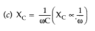
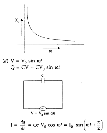
Current leads the voltage, in phase, by \(\frac{\pi}{2}\)
Question 31.
(a) Draw a labelled diagram of an ac generator.
Obtain the
expression for the emf induced in the rotating coil of N turns each of
cross-sectional area A, in the presence of a magnetic field
\(\overrightarrow{\mathbf{B}}\).
(b) A horizontal conducting rod 10 m long
extending from east to west is falling with a speed 5.0 ms-1 at right
angles to the horizontal component of the Earth’s magnetic field, 0.3 ×
10-4 Wb m-2. Find the instantaneous value of the emf
induced in the rod. (All India 2017)
Answer:
(a) Principle of A.C.
generator : The working of an a.c. generator is based on the principle of
electromagnetic induction. When a closed coil is rotated in a uniform magnetic
field with its axis perpendicular to the magnetic field, the magnetic flux
linked with the coil changes and an induced emf and hence a current is set up in
it.
(b) Let N = number of turns in the coil
A = Area of face of each turn
B
= magnitude of the magnetic field
θ = angle which normal to the coil makes
with field B at any instant
ω = the angular velocity with which coil
rotates
The magnetic flux linked with the coil at any instant f will
be,
ϕ = NAB cos θ = NAB cos ωt
By Faraday’s flux rule, the induced emf is
given by,
When a load of resistance R is connected across the terminals, a current I flows
in the external circuit.
(b) Given : l = 10 m, v = 5.0 ms-1,
B = 0.3 × 10⁻⁴
wb m-2
Induced emf = B/V
∴ E = (0.3 × 10-4) × (10) ×
(5) volt
E = 1.5 × 10⁻³ V = 1.5 mV
Question 31 a.
In the given circuit, calculate
(a) the capacitance of the
capacitor, if the power factor of the circuit is unity,
(b) the Q-factor of
this circuit. What is the significance of the Q-factor in a.c. circuit? Given
the angular frequency of the a.c. source to be 100/s. Calculate the average
power dissipated in the circuit. (Comptt. Delhi 2017)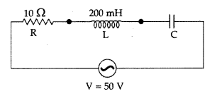
Answer: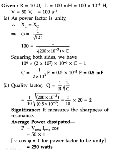
Question 32.
(a) Prove that the current flowing through an ideal inductor
connected across a.c. source, lags the voltage in phase by
\(\frac{\pi}{2}\).
(b) An inductor of self inductance 100 mH, and a bulb are
connected in series with a.c. source of rms voltage 10 V, 50 Hz. It is found
that effective voltage of the circuit \(\frac{\pi}{4}\). Calculate the
inductance of the inductor used and average power dissipated in the circuit, if
a current of 1 A flows in the circuit. (Comptt. Delhi)
Answer: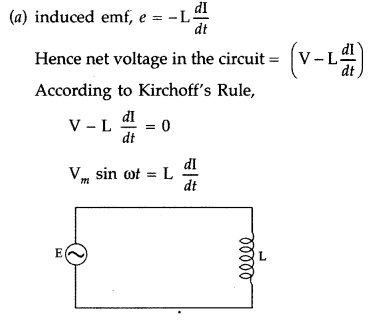
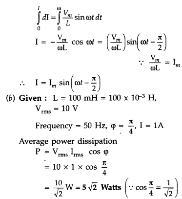
Question 33.
(a) Prove that an ideal capacitor in an ac circuit does not
dissipate power.
(b) An inductor of 200 mH, capacitor of 400 f and a resistor
of 10 Q are connected in series to ac source of 50 V of variable frequency.
Calculate the
(i) angular frequency at which maximum power dissipation occurs
in the circuit and the corresponding value of the effective current, and
(ii)
value of Q-factor in the circuit. (Comptt. All India 2017)
Answer: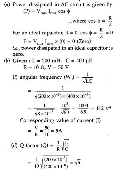
Question 34.
What is meant by impedance? Give its unit. Using a phasors
diagram or otherwise derive the expression for the Impedance of an ac circuit
containing L, C, and R in series. Find the expression for the resonant
frequency.
Answer:
It is the opposition offered by LR or CR or LCR circuit
to the flow of ac. It is measured in ohm.
For derivation of Z = \(\sqrt{R^{2}+\left(X_{L}-X_{C}\right)^{2}}\)
The impedance Z of the circuit is defined as
Z =
\(\sqrt{R^{2}+\left(X_{L}-X_{c}\right)^{2}}\)
The graph is shown.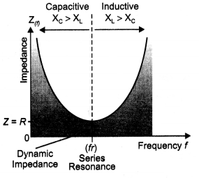
The current through an LCR circuit is given by the expression lv =
\(\frac{E_{v}}{Z}\)
where Z is the impedance. Substituting the value of Z in the above equation
we have
lv =
\(\frac{E_{v}}{\sqrt{R^{2}+\left(X_{L}-X_{C}\right)^{2}}}\)
Because the impedance depends on the frequency of the source, we see that the
current in the LCR circuit will depend upon frequency. The current, therefore,
reaches its maximum value when the impedance is minimum. This happens when
XL = XC, corresponding to Z = R. The frequency ω at which
this occurs is called resonant angular frequency. To find ω0, we use the
condition XL = XC, from which we get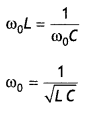
But ωo = 2 πfo, where fo is called resonance
frequency. Therefore, the above equation becomes fo = \(\frac{1}{2
\pi} \frac{1}{\sqrt{L C}}\)
Question 35.
Explain the term ‘inductive reactance’. Show graphically the
variation of an inductive reactance with the frequency of the applied
alternating voltage.
An ac voltage E = Eo sin ωt is applied across
a pure inductor of inductance L. Show mathematically that the current flowing
through it lags behind the applied voltage by a phase angle of π/2.
Answer:
It is the opposition offered to the flow of current by a pure
inductor.
Consider an ac circuit consisting of a pure Inductor connected to the
terminaLs of an ac source. Let the Instantaneous value of the ac source be
V
= Vm sin ωt ….(1)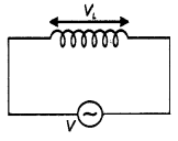
Let VL be the instantaneous voltage drop across the inductor, then
Kirchoff’s loop rule when applied to the circuit gives V + VL = 0
or
V – L\(\frac{di}{dt}\) = 0 …(2)
since VL = – L\(\frac{di}{dt}\)
Using equations (1) and (2) we
have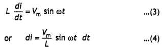
Integrating the above equation we have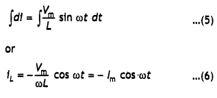
where \(\frac{V_{m}}{\omega L}\) = lm , ωL = 2πfL has the
dimensions of resistance and is called the inductive reactance of the circuit.
Using the trigonometric identity cos ωt = – sin (ωt – π/2) in equation (6) we
have
lL =lm sin (ωt – π/2) …(7)
Comparing equation
(1) with equation (7) we see that the current lags voltage by π/2 radian or
90°.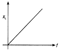
Question 36.
Explain the term ‘capacitive reactance’. Show graphically the
variation of a capacitive reactance with the frequency of the applied
alternating voltage.
An ac voltage E=Eo sin cot is applied across
a pure capacitor of capacitance C. Show mathematically that the current flowing
through it leads the applied voltage by a phase angle of π/2.
Answer:
It
is the opposition offered to the flow of current by a pure capacitor.
Consider an ac circuit consisting of a capacitor connected to an ac source. Let
the instantaneous value of emf be
V = Vm sin ωt …(1)
Let Vc be the instantaneous voltage drop across the capacitor, then by
Kirchoff’s loop rule,
V – VC = 0
V = VC = Vm Sin ωt
…(2)
But from the definition of capacitance, VC = Q / C or Q=
VCC. Substituting for VC we have
Q = C Vm
sin ωt …(3)
Differentiating equation (3) with respect to time we have,
\(\frac{d Q}{d
t}=\frac{d}{d t}\)CVm sin ωt = ω C Vm cos ωt …(4)
But dQ/dt = lc, therefore the above equation becomes,
lC = ω C
Vm cos ωt = lm cos ωt …(5)
where
lm =
\(\frac{v_{m}}{\frac{1}{\omega C}}\)
Here the term \({\frac{1}{\omega C}}\) has the dimensions of resistance and is called the capacitive reactance of the circuit and ωCVm = lm.
Using the trigonometric identity cos ωt = sin (ωt + π/2), equation (5) can be
written as
lC = lm sin (ωt + π/2) …..(6)
Comparing this expression with equation (1)
we see that the current is 90° (π/2) out of phase with the voltage across the capacitor. In other words, currently leads emf by 90°.
The graph of variation of XC with f is as shown.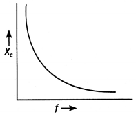
Question 37.
Derive an expression for the impedance of a series LCR circuit
connected to an ac supply of variable frequency. Plot a graph showing a
variation of current with the frequency of the applied voltage. Explain briefly
how the phenomenon of resonance in the circuit can be used in the tuning
mechanism of a radio or a TV set. (CBSE Delhi 2011)
Answer:
The voltages
across the various elements are drawn as shown in the figure below.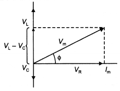
From the diagram, we observe that the vector sum of the voltage amplitudes
VR, VL, and VC equals a phasor whose length is
the maximum applied voltage Vm, where the phasor Vm makes
an angle Φ with the current phasor lm. Since the voltage phasors, VL
and VC are in opposite directions, a different phasor
(VL – VC) is drawn which is perpendicular to the phasor
VR.
Adding vectorially, we have
Vm =
\(\sqrt{V_{R}^{2}+\left(V_{L}-V_{c}\right)^{2}}\)
= \(\sqrt{\left(l_{m}
R\right)^{2}+\left(l_{m} X_{L}-l_{m} X_{c}\right)^{2}}\) …(1)
or
Vm = lm\(\sqrt{R^{2}+\left(X_{L}-X_{c}\right)^{2}}\) …(2)
where XL = ω L and XC = 1/ω C, therefore we can express
the maximum current as
lm =
\(\frac{V_{m}}{\sqrt{R^{2}+\left(X_{L}-X_{c}\right)^{2}}}\) …(3)
∴ lm = \(\frac{V_{m}}{Z}\)
The impedance Z of the circuit is defined as
Z =
\(\sqrt{R^{2}+\left(X_{L}-X_{c}\right)^{2}}\)
The graph is shown.
The graph is as shown.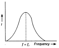
The antenna of a radio accepts signals from many broadcasting stations. The
signals picked up in the antenna act as a source in the tuning circuit of the
radio, so the circuit can be driven at many frequencies. But to hear one
particular radio station, we tune the radio. In tuning, we vary the capacitance
of a capacitor in the tuning circuit such that the resonant frequency of the
circuit becomes nearly equal to the frequency of the radio signal received. When
this happens, the amplitude of the current with the frequency of the signal of
the particular radio station in the circuit is maximum and that particular radio
station is tuned in.
Question 38.
A device ‘X’ is connected to an ac source V = Vo
sin ωt. The variation of voltage, current, and power in one cycle is shown in
the following graph.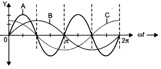
(a) Identify the device ‘X’.
Answer:
Capacitor
(b) Which of the curves A, B, and C represent the voltage, current, and power
consumed in the circuit? Justify your answer.
Answer:
A: Power, B:
Voltage, and C: Current.
(c) How does its impedance vary with the frequency of the ac source? Show
graphically.
Answer:
For a capacitor, Impedance is given by XC
= 1 /ωC = 1 /2πfC. This is shown graphically as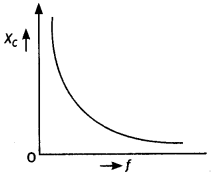
(d) Obtain an expression for the current in the circuit and its phase relation
with ac voltage. (CBSE AI 2017)
Answer:
Consider an ac circuit consisting
of a capacitor connected to an ac source. Let the instantaneous value of emf
be
V = Vo sin ωt …(1)
Let Vc be the instantaneous voltage drop across the capacitor, then by
Kirchoff’s loop rule,
V – VC = 0
or
V = VC =
Vo sin ωt …(2)
But from the definition of capacitance,
VC = Q / C
or
Q=
VC C.
Substituting for Vc we have
Q = CVo sin ωt …(3)
Differentiating equation (3) with respect to time we have,
\(\frac{d Q}{d
t}=\frac{d}{d t}\) CVo sin ω t = ω C Vo cos ω t …(4)
But dQ/dt = ic, therefore the above equation becomes,
ic = ω C Vo cos ω t = lo cos ω t …(5)
Here the term 1/ωc has the dimensions of resistance and is called the
capacitive reactance of the circuit and ωCVm = lm. Using
the trigonometric identity cos ω t = sin (ω t + π/2) equation (5) can be written
as
ic = lo sin (ω t + π/2) …(6)
Comparing this expression with equation (1) we see that the current is 90° (π/2 ) out of phase with the voltage across the capacitor. In other words, currently leads emf by 90°.
Question 39.
A device X is connected across an ac source of voltage V =
Vo sin ωt. The current through X is given as l = lo sin
(ωt + π/2).
(a) Identify the device X and write the expression for Its
reactance.
(b) Draw graphs showing the variation of voltage and current with
time over one cycle of ac, for X.
(c) How does the reactance of device X vary
with the frequency of the ac? Show this variation graphically.
(d) Draw the
phasor diagram for the device X. (CBSE AI 2018, Delhi 2018)
Answer:
(a) X:
capacitor
Reactance XC = 1 / ωC = 1 /
2πfC
(b) The graphs area as shown.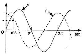
(c) Reactance of the capacitor varies in inverse proportion to the frequency.
Therefore, the graph is as shown.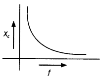
(d) The phasor diagram is as shown.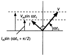
Question 40.
A resistor of 200 Ω and a capacitor of 15.0 μF is connected In
series to a 220 V, 50 Hz ac source, (a) Calculate the current in the circuit;
(b) Calculate the voltage (rms) across the resistor and the capacitor. Is the
algebraic sum of these voltages more than the source voltage? If yes, resolve
the paradox. (NCERT, CBSE Delhi 2004)
Answer:
Given R = 200 Ω, C= 15.0 μF
= 15.0 × 10⁻⁶ F, V = 220 V, f = 50 Hz
(a) In order to calculate
the current, we need the impedance of the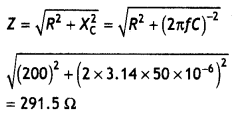
Therefore the current in the circuit is
l = \(\frac{V}{Z}=\frac{220}{291.5}\)
= 0.7555 A
(b) Since the current is the same throughout the circuit we have
VR = IR = 0.755 × 200 = 151 V
VC =
lXC = 0.755 × 212.3 = 160.3 V
The algebraic sum of the two voltages VR and Vc is 311.3 V which is more than
the source voltage of 220 V. How to resolve this paradox? As you have learned in
the text, the two voltages are not in the same phase. Therefore, they cannot be
added like ordinary numbers. The two voltages are out of phase by ninety
degrees. Therefore, the total of these voltages must be obtained using the
Pythagorean theorem;
V = \(\sqrt{V_{R}^{2}+V_{C}^{2}}\) = 220 V
Thus if the phase difference between two voltages is properly taken into account, the total voltage across the resistor and the capacitor is equal to the voltage of the source.
Question 41.
Explain why the reactance offered by an inductor increases
with the increasing frequency of an alternating voltage.
(NCERT Exemplar)
Answer:
An inductor opposes the flow of current through it by developing a
back emf according to Lenz’s law. The induced voltage has a polarity so as to
maintain the current at its present value. If the current is decreasing, the
polarity of the induced emf will be so as to increase the current and vice
versa. Since the induced emf is proportional to the rate of change of current,
it will provide greater reactance to the flow of current if the rate of change
is faster, i.e. if the frequency is higher. The reactance of an Inductor,
therefore, is proportional to the frequency, being given by ωL.
Question 42.
(a) Prove that an Ideal capacitor in an ac circuit does not
dissipate power.
Answer:
Consider an ac circuit consisting of a capacitor
connected to an ac source. Let the instantaneous value of emf be
V =
Vm sin ωt …(1)
Let Vc be the instantaneous voltage drop across the capacitor, then by
Kirchoff’s loop rule,
V – VC = 0
V = VC =
Vm Sin ωt …(2)
But from the definition of capacitance, VC = Q / C or Q=
VCC. Substituting for Vc we have
Q = C Vm sin ωt
…(3)
Differentiating equation (3) with respect to time we have,
\(\frac{d Q}{d
t}=\frac{d}{d t}\)CV<sub>m</sub> sin ωt = ω C Vm cos ωt
…(4)
But dQ/dt = lc, therefore the above equation becomes,
lC = ω C
Vm cos ωt = lm cos ωt …(5)
where
lm =
\(\frac{v_{m}}{\frac{1}{\omega C}}\)
Here the term \({\frac{1}{\omega C}}\) has the dimensions of resistance and is called the capacitive reactance of the circuit and ωCVm = lm.
Using the trigonometric identity cos ωt = sin (ωt + π/2), equation (5) can be
written as
lC = lm sin (ωt + π/2) …..(6)
Comparing this expression with equation (1)
we see that the current is 90° (π/2) out of phase with the voltage across the capacitor. In other words, currently leads emf by 90°.
The graph of variation of XC with f is as shown.
Power in capacitive circuit P = Ev lv cos Φ. In pure
captor 0 = 90° phase difference between voltage and current is π/2.
So power
consumed in pure capdtor Pav = Ev lv cos 90° =
0.
(b) An ideal inductor of 200 mH, capacitor of 400 μF, and a resistor of 10 Ω
are connected In series to an ac source of 50 V and variable frequency.
Calculate
(i)the angular frequency at which maximum power dissipation occurs
in the circuit and the corresponding value of effective current and
(ii) the
value of Q factor in the circuit. (CBSE AI 2017C)
Answer: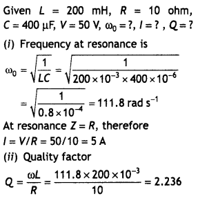
Question 43.
(a) What is the principle of transformer?
(b) Explain how
laminating the core of a transformer helps to reduce eddy current losses in
it.
(c) Why the primary and secondary coils of a transformer are preferably
wound on the same core?
Or
Show that In the free oscillations of an LC
circuit, the sum of energies stored in the capacitor and the Inductor Is
constant In time. (CBSE Sample Paper 2018-19)
Answer:
(a) It works on the
principle of mutual induction.
(b) In order to reduce the eddy current loss,
the resistance of the core should be Increased. In a transformer, the core Is
made up of thin sheets of steel, each lamination being insulated from others by
a thin layer of varnish. As the laminations are thin, they will have relatively
high resistance.
(c) This is done to maximize the sharing of magnetic flux
and also so that magnetic flux per turn should become the same in both the
primary and secondary coils.
Or
Let at any instant t, q be the charge on
the capacitor and ‘l’ be the current through the inductor
q (t) =
q0 cos ωt
i (t) = – q0 ω sin ωt
Energy stored in the
capacitor at time t is
UE = \(\frac{1}{2}
\frac{q^{2}}{c}=\frac{1}{2} \frac{q_{0}^{2}}{C}\) cos2 ωt
Energy stored in the inductor at time t is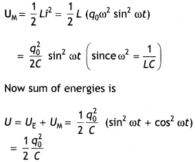
This sum is constant in time as q0 and C, both are
time-independent.
Question 44.
Explain why the reactance provided by a capacitor to an
alternating current decreases with increasing frequency. (NCERT Exemplar)
Answer:
A capacitor does not allow the flow of direct current through it as
the resistance across the gap is infinite. When an alternating voltage is
applied across the capacitor plates, the plates are alternately charged and
discharged. The current through the capacitor is a result of this changing
voltage (or charge). Thus, a capacitor will pass more current through it if the
voltage is changing at a faster rate, i.e. if the frequency of the supply is
higher. This implies that the reactance offered by a capacitor is less with
increasing frequency; it is given by 1 /ωC.
Question 45.
(a) With the help of a labeled diagram, describe briefly the
underlying principle and working of a step-up transformer.
(b) Write any two
sources of energy loss in a transformer.
(c) A step-up transformer converts a
low input voltage into a high output voltage. Does it violate the law of
conservation of energy? Explain. (CBSE Delhi 2011)
Answer:
(a) The diagram
is as shown.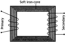
It works on the principle of mutual induction i.e., whenever magnetic flux
linked with a coil changes an emf is induced in the neighboring coil. In a
step-up transformer, the number of turns in the secondary is more than that in
the primary.
The ac source causes an alternating current in the primary, which sets up an alternating flux in the core; this induces an emf in each winding of the secondary, in accordance with Faraday’s law. The induced emf in the secondary gives rise to an alternating current in the secondary, and this delivers energy to the device to which the secondary is connected.
For step up : Ns> > Np
\(\frac{\varepsilon_{s}}{\varepsilon_{p}}=\frac{N_{s}}{N_{p}}\) and
\(\frac{\varepsilon_{\mathrm{s}}}{\varepsilon_{\mathrm{p}}}=\frac{l_{\mathrm{p}}}{l_{\mathrm{s}}}\)
(b) Two major sources of energy loss in this device are:
- Heat produced due to production of eddy currents.
- Copper loss: heat produced in the copper coils
(c) No, a transformer does not change the power. Thus if a voltage increases current gets decreased such that the energy and power remain the same.
Question 46.
(a) Explain with the help of a labeled diagram, principle,
and working of a transformer. Deduce the expression for its working formula.
Answer:
For diagram as shown.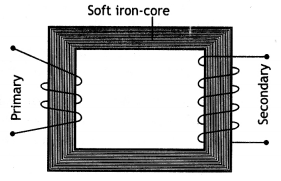
- Principle: A transformer works on the basis of mutual induction.
- Working: In a 100% efficient transformer
εs ls = εp lp where l and
lp, are the secondary and primary currents, therefore we have
\(\frac{\varepsilon_{\mathrm{s}}}{\varepsilon_{\mathrm{p}}}=\frac{l_{\mathrm{p}}}{l_{\mathrm{s}}}\)
….(1)
Now a 1oo % efficient transformer
we have
\(\frac{\varepsilon_{\mathrm{s}}}{\varepsilon_{\mathrm{p}}}=\frac{N_{\mathrm{s}}}{N_{\mathrm{p}}}
\frac{\frac{d \phi}{d t}}{\frac{d \phi}{d
t}}=\frac{N_{\mathrm{s}}}{N_{\mathrm{p}}}\) …(2)
Therefore form (1) and (2) we have
\(\frac{N_{\mathrm{s}}}{N_{\mathrm{p}}}=\frac{l_{\mathrm{p}}}{l_{\mathrm{s}}}\)
= k
Efficiency of transformer = \(\frac{V_{s} I_{s}}{V_{p} I_{p}}\).
(b) Name any four causes of energy loss in an actual transformer. (CBSEAI
2013C)
Answer:
- Copper loss
- Iron loss
- Flux loss
- Hysteresis loss
Question 47.
(a) Draw a schematic sketch of an ac generator describing its
basic elements. State briefly its working principle. Show a plot of the
variation of (i) Magnetic flux and alternating emf versus time generated by a
loop of wire rotating in a magnetic field,
Answer:
A schematic sketch is
as shown.
Working principle: Electromagnetic induction.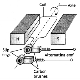
The graphs are as shown.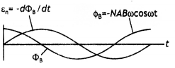
(b) Why is a choke coil needed in the use of fluorescent tubes with ac mains?
(CBSE Delhi 2014)
Answer:
It is used to regulate current with minimum loss
of energy.
Question 48.
(a) Draw a labeled diagram of the AC generator. Derive the
expression for the instantaneous value of the emf induced in the coil.
Answer:
It is based on the principle of electromagnetic induction. When a
coil is rotated about an axis perpendicular to the direction of the uniform
magnetic field, an induced emf is produced across it.
Working: The working of the ac generator can be understood with the help of
the various positions of the armature as shown in the figure below.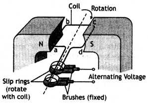
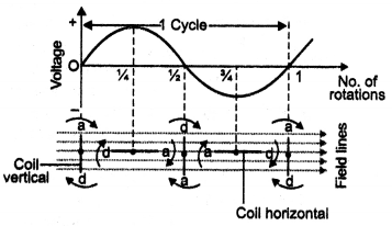
Suppose at time t = 0, the plane of the loop is perpendicular to B. As the loop
rotates from position t = 0 to position t T/2, the Induced emf changes from zero
to maximum value and then becomes zero again as shown in the diagram For angles
0° and 1800 the instantaneous rate of magnetic flux is zero, hence induced emf
Is zero.
As the Loop moves from position t = T/2 to position t = T, the emf again changes from zero to the maximum value and then again becomes zero. But this time it reverses Its direction. For angles 90° and 270° maximum magnetic flux are linked with the coil hence the emf is a maximum. Thus the output of the ac generator varies sinusoidally with time. The Induced emf does not depend upon the shape of the Loop but depends only upon the area of the loop.
The emf generated Is given by the expression ε = nBAω Sin ωt, where ω is the speed of rotation of the coil
(b) A circular coil of cross-sectional area 200 cm2 and 20 turns
is rotated about the vertical diameter with an angular speed of 50 rad
s-1 in a uniform magnetic field of magnitude 3.O × 10-2 T.
Calculate the maximum value of the current in the coil. (CBSE Delhi 2017)
Answer:
Given A = 200 cm2, ω = 50 rad s-1, n = 20
S
= 3 × 10⁻² T, εo = ?,
Using the relation ε0 = nBAω
= 20 × 3 × 10-2 × 200 ×
10-4 × 50 = 0.6 V
Question 49.
Draw a labeled diagram of a step-up transformer. Obtain the
ratio of secondary to primary voltage in terms of the number of turns and
currents in the two coils.
A power transmission line feeds input power at
2200 V to a step-down transformer with its primary windings having 3000 turns.
Find the number of turns in the secondary to get the power output at 220 V.
(CBSE Delhi 2017)
Answer:
(a) The diagram is as shown.
It works on the principle of mutual induction i.e., whenever magnetic flux
linked with a coil changes an emf is induced in the neighboring coil. In a
step-up transformer, the number of turns in the secondary is more than that in
the primary.
The ac source causes an alternating current in the primary, which sets up an alternating flux in the core; this induces an emf in each winding of the secondary, in accordance with Faraday’s law. The induced emf in the secondary gives rise to an alternating current in the secondary, and this delivers energy to the device to which the secondary is connected.
For step up : Ns > Np
\(\frac{\varepsilon_{s}}{\varepsilon_{p}}=\frac{N_{s}}{N_{p}}\) and
\(\frac{\varepsilon_{\mathrm{s}}}{\varepsilon_{\mathrm{p}}}=\frac{l_{\mathrm{p}}}{l_{\mathrm{s}}}\).
Principle – It works on the principle of electromagnetic induction. When the current in one circuit changes, an induced current is set up in the neighboring circuit.
(b) Ns = ?, Np = 3000
Ep = 2200 V,
Es = 220 V
Since, Es/Ep = Ns/Np
220/2200
= Ns/3000
Ns = 300
Question 50.
(a) State the principle of working of a transformer.
Answer:
It works on the principle of mutual inductance i.e. whenever the
magnetic flux Linked in a coil changes an induced emf Is produced in the
neighboring coil.
(b) Define the efficiency of a transformer.
Answer:
It is the ratio of
the output power to the input power.
(c) State any two factors that reduce the efficiency of a transformer.
Answer:
Copper Loss, flux Loss
(d) Calculate the current drawn by the primary of a 90% efficient transformer
which steps down 220 V to 22 V If the output resistance Is 440 Ω. (CBSFAI 2018
C)
Answer:
Given η = 90%, Vp = 22OV, Vs = 22V,
Ro = 440 W
Now ls = Vs/R = 22/440 = 0.05
A
Also η = \(\frac{P_{0}}{P_{1}}=\frac{V_{s} l_{s}}{V_{p} l_{p}}\) , therefore we have
\(\frac{90}{100}=\frac{22 \times 0.05}{220 \times l_{\mathrm{p}}}\)
or
lp = 0.0056 A
Question 51.
Draw an arrangement for winding of primary and secondary coil
In a transformer with two coils on a separate limb of the core.
State the
underlying principle of a transformer. Deduce the expression for the ratio of
secondary voltage to the primary voltage In terms of the ratio of the number of
turns of the primary and secondary winding. For an ideal transformer, obtain the
ratio of primary and secondary currents In terms of the ratio al the voltages in
the secondary and primary voltages. Write any two reasons for the energy losses
which occur In actual transformers, (CBSE Dei hi 2016C)
Answer:
Principle:
When an alternating voltage is applied to the primary, the resulting current
produces an alternating magnetic flux which Links the secondary and Induces an
emf in it.
Induced emf, or voltage, in the secondary, with ‘Ns‘ number of
turns,
εs = – Ns \(\frac{d \phi}{d t}\)
Back emf In the primary with Np turns,
εp = – Np
\(\frac{d \phi}{d t}\)
Since εs = Vs and εp = Vp
Therefore we have
\(\frac{V_{p}}{V_{s}}=\frac{N_{p}}{N_{s}}\)
For an ideal transformer,
Input power = output power
Therefore
lpVp = lsVs
Or
\(\frac{V_{p}}{V_{s}}=\frac{l_{s}}{l_{p}}\)
(a) Heat energy Loss.
(b) Humming effect Loss.
Question 52.
A pure inductor is connected across an ac source. Show
mathematically that the current in it lags behind the applied emf by a phase
angle of π/2. What is its inductive reactance? Draw a graph showing the
variation of an inductive reactance with the frequency of the ac source.
Answer:
Consider an ac circuit consisting of a pure Inductor connected to the
terminaLs of an ac source. Let the Instantaneous value of the ac source be
V
= Vm sin ωt ….(1)
Let VL be the instantaneous voltage drop across the inductor, then
Kirchoff’s loop rule when applied to the circuit gives V + VL = 0
or
V – L\(\frac{di}{dt}\) = 0 …(2)
since VL = – L\(\frac{di}{dt}\)
Using equations (1) and (2) we
have
Integrating the above equation we have
where \(\frac{V_{m}}{\omega L}\) = lm , ωL = 2πfL has the
dimensions of resistance and is called the inductive reactance of the circuit.
Using the trigonometric identity cos ωt = – sin (ωt – π/2) in equation (6) we
have
lL =lm sin (ωt – π/2) …(7)
Comparing equation
(1) with equation (7) we see that the current lags voltage by π/2 radian or
90°.
Question 53.
An alternating emf Is applied across a capacitor. Show
mathematically that the current leads the emf by a phase angle π/2, What Is its
capacitive reactance? Draw a graph showing the variation of a capacitive
reactance with the frequency of the ac source.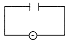
Answer:
Consider an ac circuit consisting of a capacitor connected to an ac
source. Let the instantaneous value of emf be
V = Vm sin ωt
…(1)
Let Vc be the instantaneous voltage drop across the capacitor, then by
Kirchoff’s loop rule,
V – VC = 0
V = VC =
Vm Sin ωt …(2)
But from the definition of capacitance, VC = Q / C or Q=
VCC. Substituting for VC we have
Q = C Vm
sin ωt …(3)
Differentiating equation (3) with respect to time we have,
\(\frac{d Q}{d
t}=\frac{d}{d t}\)CVm sin ωt = ω C Vm cos ωt …(4)
But dQ/dt = lC, therefore the above equation becomes,
lC = ω C Vm cos ωt = lm cos ωt …(5)
where
lm = \(\frac{v_{m}}{\frac{1}{\omega C}}\)
Here the term \({\frac{1}{\omega C}}\) has the dimensions of resistance and is called the capacitive reactance of the circuit and ωCVm = lm.
Using the trigonometric identity cos ωt = sin (ωt + π/2), equation (5) can be
written as
lC = lm sin (ωt + π/2) …..(6)
Comparing this expression with equation (1)
we see that the current is 90° (π/2) out of phase with the voltage across the capacitor. In other words, currently leads emf by 90°.
The graph of variation of XC with f is as shown.
Question 54.
(a) In a series LCR circuit connected across an ac source of
variable frequency, obtain the expression for its impedance and draw a plot
showing its variation with the frequency of the ac source.
Answer:
The
voltages across the various elements are drawn as shown in the figure
below.
From the diagram, we observe that the vector sum of the voltage amplitudes
VR, VL, and VC equals a phasor whose length is
the maximum applied voltage Vm, where the phasor Vm makes an angle Φ with the
current phasor lm. Since the voltage phasors, VLand VC is
in opposite directions, a different phasor (VL – VC) is
drawn which is perpendicular to the phasor VR.
Adding vectorially, we have
Vm =
\(\sqrt{V_{R}^{2}+\left(V_{L}-V_{c}\right)^{2}}\)
= \(\sqrt{\left(l_{m}
R\right)^{2}+\left(l_{m} X_{L}-l_{m} X_{c}\right)^{2}}\) …(1)
or
Vm = lm\(\sqrt{R^{2}+\left(X_{L}-X_{c}\right)^{2}}\)
…(2)
where XL = ω L and XC = 1/ω C, therefore we can express
the maximum current as
lm =
\(\frac{V_{m}}{\sqrt{R^{2}+\left(X_{L}-X_{c}\right)^{2}}}\) …(3)
∴ lm = \(\frac{V_{m}}{Z}\)
The impedance Z of the circuit is defined as
Z =
\(\sqrt{R^{2}+\left(X_{L}-X_{c}\right)^{2}}\)
The graph is shown.
(b) What is the phase difference between the voltages across the inductor and
the capacitor at resonance in the LCR circuit?
Answer:
The phase
difference between the voltage across the inductor and the capacitor at
resonance is 180°.
(c) When an inductor is connected to a 200V dc voltage, a current of 1A flows
through it. When the same inductor is connected to a 200V, 50 Hz ac source, only
0.5A current flows. Explain why? Also, calculate the self-inductance of the
inductor. (CBSE Delhi 2019)
Answer:
Inductor will offer an additional
impedance to ac due to its self-inductance.
Now R = \(\frac{V_{\text {rms }}}{l_{\text {rms }}}=\frac{200}{1}\) = 200 Ω
The impedance of the inductor
Z =
\(\frac{V_{\mathrm{rms}}}{l_{\mathrm{rms}}}=\frac{200}{0.5}\) = 400 Ω
Now Z = \(\sqrt{R^{2}+X_{L}^{2}}\) , therefore
XL2 =
Z2 – R2
XL =
\(\left(\sqrt{(400)^{2}-(200)^{2}}\right)\) = 346.4 Ω
Hence inductance (L) is
L = \(\frac{X_{L}}{\omega}=\frac{346.4}{2 \times
3.14 \times 50}\) = 6.2 H
Question 55.
(a) Obtain the expression for the average power dissipated in
a series LCR circuit driven by an ac source of voltage V = Vm sin ωt
supplying the current i = im sin (ωt + Φ).
Answer:
Average
Power dissipated in a series LCR circuit
Given V = Vm sin tot
And l = im sin (ωt + Φ)
Instantaneous Power
P = Vi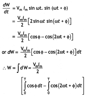
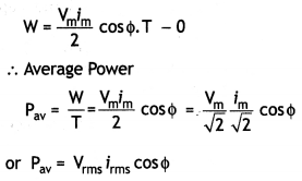
(b) Define the terms:
(i) Wattless current, and
Answer:
Wattles’s
current: If the average power consumed due to the flow of current in a circuit
is zero, the current is said to be wattless.
(ii) Q – a factor of LCR circuit.
Answer:
Q-factor of an LCR Circuit:
Q-factor of the LCR circuit is the ratio of the potential difference across
inductance (or capacitance) at resonance to the applied voltage.
Question 56.
Distinguish between the terms reactance and impedance of an
ac circuit. Prove that an ideal capacitor connected to an ac source does not
dissipate power.
| S.No. Reactance | Impedance |
| 1. It is the opposition offered by a pure inductor or a pure capacitor or both to the flow of ac. | 1. It is the opposition offered by LR or CR or LCR circuit to the flow of ac |
| 2. It depends upon the frequency of ac. | 2. It depends upon the frequency of ac. |
| 3. It can be inductive or capacitive. | 3. It can be inductive, capacitive, or resistive. |
| 4. It can be zero. | 4. It can never be zero. |
Consider an ac circuit consisting of a capacitor connected to an ac source.
Let the instantaneous value of emf be
V = Vm sin ωt …(1)
Let VC be the instantaneous voltage drop across the capacitor,
then by Kirchoff’s loop rule,
V – VC = 0
V = VC =
Vm Sin ωt …(2)
But from the definition of capacitance, VC = Q / C or Q=
VCC. Substituting for Vc we have
Q = C Vm sin ωt
…(3)
Differentiating equation (3) with respect to time we have,
\(\frac{d Q}{d
t}=\frac{d}{d t}\)CVm sin ωt = ω C Vm cos ωt …(4)
But dQ/dt = lc, therefore the above equation becomes,
lC = ω C
Vm cos ωt = lm cos ωt …(5)
where
lm =
\(\frac{v_{m}}{\frac{1}{\omega C}}\)
Here the term \({\frac{1}{\omega C}}\) has the dimensions of resistance and is called the capacitive reactance of the circuit and ωCVm = lm.
Using the trigonometric identity cos ωt = sin (ωt + π/2), equation (5) can be
written as
lC = lm sin (ωt + π/2) …..(6)
Comparing this expression with equation (1)
we see that the current is 90° (π/2) out of phase with the voltage across the capacitor. In other words, current leads emf by 90°.
The graph of variation of Xc with f is as shown.
Question 57.
Define the term root mean square (rms) value of ac. Derive the
relation between rms value and the peak value of ac.
Answer:
It is that
value of steady current (dc) which when passed through a resistor in a given
time produces the same heat as is produced by the ac. when passed through the
same resistor for the same time. It is abbreviated as rms value of current. It
is denoted by lrms.
Consider an ac source. Let the instantaneous value of current be represented
by the equation
i = lm sin ωt
Let this current pass through a resistor of resistance R. Therefore in a
small-time dt, the amount of heat produced in the resistor is
dH =
i2 R dt
The total amount of heat produced in one complete cycle of ac is given
by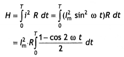
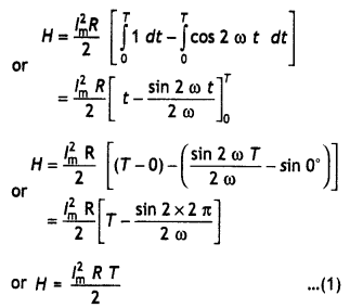
Let lrms be the virtual value of ac, then the amount of heat
produced in the same resistor of resistance R, in the same time T is
H =
lrms2RT …(2)
Therefore from equations (1) and (2) we have
lrms =
\(\frac{l_{m}}{\sqrt{2}}\) = 0.707 lm
Question 58.
(a) Prove that the current flowing through an Ideal Inductor
connected across a.c. source lags the voltage In phase by nil.
Answer:
(a)
Consider an ac circuit consisting of a pure inductor connected to the terminals
of an ac source. Let the instantaneous value of the ac source be
V =
Vm sin ω t …(1)
Let VL be the instantaneous voltage drop across the inductor, then
Kirchoff’s loop rule when applied to the circuit gives V + VL = 0
or
V – L\(\frac{di}{dt}\) = 0 …(2)
since VL = – L \(\frac{di}{dt}\)
Using equations (1) and (2) we have
L\(\frac{di}{dt}\) = Vm sin
ω t …(3)
or
di = \(\frac{V_{m}}{L}\) sin ω t dt …(4)
Integrating the above equation we have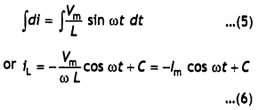
C = 0, over a period of cycle
\(\frac{V_{\mathrm{m}}}{\omega L}\) = lm, ωL = 2πfL has
the dimensions of resistance and is called the inductive reactance of the
circuit. Using the trigonometric identity
cos ω t = – sin (ωt – π/2) in
equation (6) we have
lL = lm sin (ωt – π/2) …(7)
Comparing equation (1) with equation (7) clearly shows that the current lags voltage by π/2 radian or 90°.
(b) An inductor of self-inductance 100 mH and a bulb are connected in series
with a.c. source of rms voltage 10 V, 50 Hz. It is found that the effective
voltage of the circuit leads the current in phase by π/4. Calculate the
resistance of the bulb used and average power dissipated in the circuit, if a
current of 1 A flows in the circuit. (CBSE Delhi 2017C)
Answer:
(b) V= 10
V, f = 50 Hz, l = 1.0 A, Φ = π/4, R = ?, L = 100mH = 0.1 H
Now Z = V/l =
10/1.0 = 10 ohm
Also Z = \(\sqrt{R^{2}+X_{L}^{2}}\) = 10
Now cos Φ = \(\frac{R}{Z}\)
or
Therefore, R = cos Φ × Z
Or
R = cos π/4 × 10 = 7 ohm
Power dissipated
Pav = lrms Vrms cos Φ =
\(\frac{V_{m}^{2}}{Z}\) × cos Φ
0r
Pav =
\(\frac{(10)^{2}}{10}\) × 0.707 = 7.07 W
Question 59.
(a) Draw graphs showing the variations of inductive reactance
and capacitive reactance with the frequency of the applied ac source.
(b)
Draw the phasor diagram for a series RC circuit connected to an ac source.
(c) An alternating voltage of 220 V is applied across a device X, a current of
0.25 A flows, which lag behind the applied voltage In phase by \(\frac{π}{2}\)
radian. If the same voltage is applied across another device Y, the same current
flows but now it is in phase with the applied voltage.
(i) Name the devices X
and Y.
(ii) Calculate the current flowing in the circuit when the same
voltage is applied across the series combination of X and Y. (CBSEAI 2018C)
Or
(a) State the principle of working of a transformer.
(b) Define the
efficiency of a transformer.
(c) State any two factors that reduce the
efficiency of a transformer.
(d) Calculate the current drawn by the primary
of a 90% efficient transformer which steps down 220 V to 22 V, if the output
resistance is 440 Ω.
Answer:
(a) The two graphs are as shown.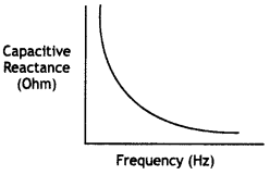
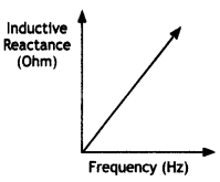
(b) (The current leads the voltage by an angle 0 where 0 < θ <
\(\frac{π}{2}\).) The required phasor diagram is as shown.
Here θ =
tan-1 \(\frac{1}{ωCR}\)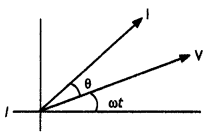
(c) In device X:
Current lags behind the voltage by \(\frac{π}{2}\)
∴ X
is an inductor.
In device Y:
Current is in phase with the applied voltage
∴ X is a
resistor.
We are given that 0.25 = \(\frac{220}{X_{L}}\)
or
XL =
\(\frac{220}{0.25}\) Ω = 880 Ω
Also 0.25 = 0.25 = \(\frac{220}{X_{R}}\)
∴ XR = \(\frac{220}{0.25}\) Ω = 880 Ω
For the series combination of X and Y, Equivalent impedance
=
\(\sqrt{X_{L}^{2}+X_{R}^{2}}\) = (880\(\sqrt{2}\) Ω
∴ Current flowing = \(\frac{220}{880 \sqrt{2}}\) A = 0.177 A
Or
(a) A
transformer works on the principle of mutual induction. (Alternatively, an emf
is induced in the secondary coil when the magnetic flux linked with it changes
with time due to changing magnetic flux linked with the primary coil).
(b) The efficiency of a transformer equals the ratio of the output power to
the input power.
Efficiency = \(\frac{\text { output power }}{\text { input
power }}\)
or
Efficiency = \(\frac{V_{S} I_{S}}{V_{P} I_{p}}\)
(c)
- Eddy current Losses
- route heat Losses
- hysteresis Losses
- magnetic flux leakage Losses
We have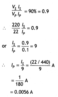
Question 60.
(a) Draw a schematic diagram of a step-up transformer.
Explain its working principle. Assuming the transformer to be 100% efficient,
obtain the relation for
(i) the current in the secondary in terms of the
current in the primary, and
(ii) the number of turns in the primary and
secondary windings.
(b) Mention two Important energy losses in actual
transformers and state how these can be minimized. (CBSE Delhi 2011C)
Answer:
(a) For diagram as shown.
- Principle: A transformer works on the basis of mutual induction.
- Working: In a 100% efficient transformer
εs ls = εp lp where l and
lp are the secondary and primary currents, therefore we have
\(\frac{\varepsilon_{\mathrm{s}}}{\varepsilon_{\mathrm{p}}}=\frac{l_{\mathrm{p}}}{l_{\mathrm{s}}}\)
….(1)
Now a 1oo % efficient transformer
we have
\(\frac{\varepsilon_{\mathrm{s}}}{\varepsilon_{\mathrm{p}}}=\frac{N_{\mathrm{s}}}{N_{\mathrm{p}}}
\frac{\frac{d \phi}{d t}}{\frac{d \phi}{d
t}}=\frac{N_{\mathrm{s}}}{N_{\mathrm{p}}}\) …(2)
Therefore form (1) and (2) we have
\(\frac{N_{\mathrm{s}}}{N_{\mathrm{p}}}=\frac{l_{\mathrm{p}}}{l_{\mathrm{s}}}\)
= k
Efficiency of transformer = \(\frac{V_{s} I_{s}}{V_{p} I_{p}}\)
(b) The two important energy losses in actual transformers are:
- Iron losses in the core of the transformer.
- Loss of energy in the primary and secondary due to Joule heating. The iron losses due to eddy currents are minimized by laminating the iron core.
Question 61.
(a) Draw the diagram of a device that is used to decrease
high ac voltage into a low ac voltage and state its working principle. Write
four sources of energy loss in this device.
Answer:
The labeled diagram is
as shown.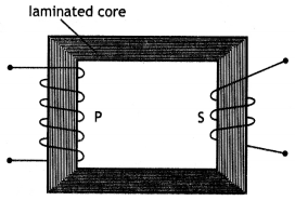
It works on the principle of mutual induction, i.e. whenever magnetic flux
linked with a coil changes, an emf is induced in the neighboring coil.
The possible causes of energy losses in transformers are:
- Flux leakage
- Copper loss
- Eddy currents
- Hysteresis loss
(b) A small town with a demand of 1200kW of electric power at 220 V is
situated 20 km away from an electric plant generating power at 440V. The
resistance of the two wirelines carrying power is 0.5 Ω per km. The town gets
the power from the line through a 4000 – 220V step-down transformer at a
sub-station in the town. Estimate the line power loss in the form of heat. (CBSE
Delhi 2019)
Answer:
Total resistance of the line = length × resistance per
unit length = 40 km × 0.5 = 20 Ω
Current flowing in the line l = P/V
= 1200 × 103 /4000 = 300
A
Power loss = l2R = (300)2 × 20 = 1800 kW
Question 62.
(a) State the principle of an ac generator and explain its
working with the help of a labeled diagram. Obtain the expression for the emf
induced in a coil having N turns each of cross-sectional area A, rotating with a
constant angular speed ‘co’ in a magnetic field B, directed perpendicular to the
axis of rotation.
Answer:
For principle and diagram
Suppose at time t = 0, the plane of the loop is perpendicular to B. As the loop
rotates from position t = 0 to position t T/2, the Induced emf changes from zero
to maximum value and then becomes zero again as shown in the diagram For angles
0° and 1800 the instantaneous rate of magnetic flux is zero, hence induced emf
Is zero. As the Loop moves from position t = T/2 to position t = T, the emf
again changes from zero to the maximum value and then again becomes zero. But
this time it reverses Its direction. For angles 90° and 270° maximum magnetic
flux are linked with the coil hence the emf is a maximum. Thus the output of the
ac generator varies sinusoidally with time. The Induced emf does not depend upon
the shape of the Loop but depends only upon the area of the loop.
The emf generated Is given by the expression ε = nBAω Sin ωt, where ω is the speed of rotation of the coiL.
(b) An airplane is flying horizontally from west to east with a velocity of
900 km h-1. Calculate the potential difference developed between the
ends of its wings having a span of 20 m. The horizontal component of the Earth’s
magnetic field is 5 × 10⁻⁴ T and the angle of dip is 30°. (CBSEAI
2018, Delhi 2018)
Answer:
Potential difference developed between the ends
of the wings
ε = BLv
Given Velocity V = 900 km h-1 = 250 m s-1
Wing span
(L1) = 20 m
Vertical component of Earth’s magnetic field
Bv = BH tan δ = 5
× 10-4 (tan 30°) T
∴ Potential difference
= 5 × 10⁻⁴ (tan 30°) × 20 × 250 = 1.44
V
Question 63.
Explain, with the help of a diagram, the principle and
working of an ac generator. Write the expression for the emf generated in the
coil in terms of its speed of rotation.
Answer:
It is based on the
principle of electromagnetic induction. When a coil is rotated about an axis
perpendicular to the direction of a uniform magnetic field, an induced emf is
produced across it.
Working: The working of the ac generator can be understood with the help of
the various positions of the armature as shown in figure below.
Suppose at time t = 0, the plane of the loop is perpendicular to B. As the loop
rotates from position t = 0 to position t T/2, the Induced emf changes from zero
to maximum value and then becomes zero again as shown in the diagram For angles
0° and 1800 the instantaneous rate of magnetic flux is zero, hence induced emf
Is zero. As the Loop moves from position t = T/2 to position t = T, the emf
again changes from zero to a maximum value and then again becomes zero. But this
time it reverses Its direction. For angles 90° and 270° maximum magnetic flux
are linked with the coil hence the emf is a maximum. Thus the output of the ac
generator varies sinusoidally with time. The Induced emf does not depend upon
the shape of the Loop but depends only upon the area of the loop.
The emf generated Is given by the expression ε = nBAω Sin ωt, where ω is the speed of rotation of the coiL.
Numerical Problems:
Formulae for solving numerical problems
- Capacitive reactance XC = \(\frac{1}{\omega C}=\frac{1}{2 \pi f C}\)
- Inductive reactance XL = ωL = 2πfL
- When ac flows through an LR circuit then,
Z = \(\sqrt{R^{2}+X_{L}^{2}}\) and tan Φ = \(\frac{X_{L}}{R}=\frac{\omega L}{R}\) - When ac flows through a CR circuit then,
Z = \(\sqrt{R^{2}+X_{C}^{2}}\) and tan Φ = \(\frac{X_{c}}{R}=\frac{1}{\omega C R}\) - For a senes LCR circuit driven by voltage V = Vm sin ωt, the
current is given by
l = lm sin (ωt + Φ) where
lm = \(\frac{V_{m}}{\sqrt{R^{2}+\left(X_{L}-X_{C}\right)^{2}}}\) - The impedance of this circuit is given by
Z = \(\sqrt{R^{2}+\left(X_{L}-X_{C}\right)^{2}}\)
\(\frac{V_{s}}{V_{p}}=\frac{N_{s}}{N_{p}}=\frac{I_{p}}{I_{s}}\) = k.
Question 1.
The figure shows how the reactance of an Inductor varies with
frequency. (a) Calculate the value of the Inductance of the Inductor using
Information given In the graph. (b) If this Inductor is connected In senes to a
resistor of 8 ohms, find what would be the impedance at 300 Hz.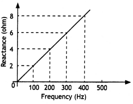
Answer:
(a) We know that XL = 2πfL or L = \(\frac{X_{L}}{2 \pi
f}\).
Now slope of the graph is
\(\frac{X_{L}}{f}=\frac{8-6}{400-300}=\frac{2}{100}\) = 0.02
Therefore L is L = \(\frac{X_{L}}{2 \pi f}=\frac{0.02}{2 \times 3.14}\) = 0.0032 H
(b) NowR = 8 ohm, f = 300 Hz, Z = ?
Now Z = \(\sqrt{R^{2}+X_{L}^{2}}\) .
Therefore we have
Z = \(\sqrt{R^{2}+X_{L}^{2}}\) = \(\sqrt{(8)^{2}+(6)^{2}}\)
= 10 Ω
Question 2.
A 25.0 μF capacitor, a 0.10-henry Inductor, and a 25.0-ohm
resistor are connected in series with an ac source whose emf is E= 310 s. In 314
t (i) what is the frequency of the .mf? (ii) Calculate (a) the reactance of the
circuit (b) the Impedance of the circuit and (C) the current in the circuit.
Answer:
Given C = 25.0 μF, L = 0.10 henry, R = 25.0 ohm, Eo =
310V,
Comparing with the equation E = Eo sin ωt,
we have
(i)
ω = 314 or f = 50 Hz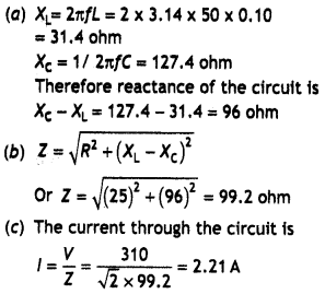
Question 3.
A sinusoidal voltage V = 200 sin 314 t Is applied to a
resistor of 10 ohms. Calculate (i) rms value of current (ii) rms value of
voltage and (iii) power dissipated as heat in watt.
Answer:
Vo
= 200 V, ω = 314 rads-1 , Vrms = ?, lrms = ?, P
= ?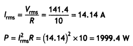
Question 4.
Find the inductance of the inductor used in series with a bulb
of resistance 10 ohms connected to an ac source of 80 V, 50 Hz. The power factor
of the circuit is 0.5. Also, calculate the power dissipation in the circuit.
Answer:
Given R = 10 ohm, V = 80 Hz, f = 50 Hz, cos Φ = 0.5 , L = ?, P =
?
Using the formula
cos Φ = \(\frac{R}{\sqrt{R^{2}+X_{L}^{2}}}\)
or
0.25(R2 + X2) = R2
Or
O.25XL2 = O.75R2
or
XL = 17.32
ohm
Now using XL = 2πfL we have
L = \(\frac{X_{L}}{2 \pi
f}=\frac{17.32}{2 \times 3.14 \times 50}\) = 0.055 H
Now Z = \(\sqrt{R^{2}+X_{L}^{2}}\)
= \(\sqrt{(10)^{2}+(17.32)^{2}}\) = 20
Ω
Now Pav = lrms Vrms cos Φ =
\(\frac{V_{m}^{2}}{Z}\) × cos Φ
or
Pav = \(\frac{(80)^{2}}{2 \times 20}\)
× 0.5 = 160 W
Question 5.
When an alternating voltage of 220 V is applied across a
device X, a current of 0.5 A flows through the circuit and Is in phase with the
applied voltage. When the same voltage is applied across a device Y, the same
current again flows through it, but it leads the voltage by π/2. If element ‘X’
is a pure resistor of 100 ohms,
(a) name the circuit element ‘Y’ and
Answer:
The element Y is a capacitor.
(b) calculate the rms value of current, if rms value of voltage is 141 V.
Answer:
The value of Xc is obtained as below
XC = \(\frac{V}{I}=\frac{220}{0.5}\) = 440 ohm
Therefore impedance of the circuit
Z =
\(\sqrt{R^{2}+X_{C}^{2}}=\sqrt{(100)^{2}+(440)^{2}}\) = 451.2 ohm
Therefore rms value of current V 141
l = \(\frac{V_{r m
s}}{Z}=\frac{141}{451.2}\) = 0.3125 A
Question 6.
When an alternating voltage of 220 V is applied across a
device X, a current of 0. 5 A flows through the circuit and is in phase with the
applied voltage. When the same voltage is applied across a device V, the same
current again flows through it, but it lags the voltage by π/2.
(a) Name the
devices X and Y.
Answer:
The element X is a resistor and Y is an
inductor.
(b) Calculate the current flowing through the circuit when the same voltage
is applied across the series combination of the two devices X and Y.
Answer:
Now both R and XL are the same and are given by
R = XL
= \(\frac{220}{0.5}\) = 440 ohm
Hence impedance of the circuit
Z = \(\sqrt{R^{2}+X_{L}^{2}}\)
=
\(\sqrt{(440)^{2}+(440)^{2}}\)
= 622.2 ohm
Therefore current flowing through the circuit is
l = \(\frac{V}{Z}\) =
\(\frac{220}{622.2}\) = 0.353 A
Question 7.
A 15.0 μF capacitor Is connected to a 220 V, 50 Hz source.
Find the capacitive reactance and the current (rms and peak) In the circuit. If
the frequency Is doubled, what happens to the capacitive reactance and the
current?
Answer:
Given C= 15.0 μF= 15 × 10-6 F, V= 220 V,
f
= 50 HZ, XC = ? lm = ?
The capacitive reactance is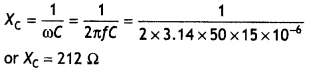
Now lrms = \(\frac{V_{r m s}}{X_{c}}=\frac{220}{212}\) = 1.04 A
Peak value of current
lm = \(\sqrt{2}\) × lrms = 1.4.1 × 1.04 =
1.47 A
This current oscillates between + 1.47A and – 1.47 A, and is ahead of the voltage by π/2.
If the frequency is doubled, the capacitive reactance is halved and consequently, the current is doubled.
Question 8.
A sinusoidal voltage of peak value 283 V and frequency 50 Hz
is applied to a series LCR circuit in which R = 3 Ω, L = 25.48 mH and C = 796
μF. Find
(a) the impedance of the circuit;
(b) the phase difference
between the voltage across the source and the current;
(c) the power
dissipated in the circuit; and
(d) the power factor.
Answer:
Given
Vm = 283 V, f = 50 Hz, R = 3 Ω
L = 25.48 mH, and C = 796 μF.
(a) To find the impedance of the circuit, we first calculate XL and Xc
XL = 2πfL = 2 × 3.14 × 50 × 25.48 × 10-3 = 8 Ω
XC = \(\frac{1}{2πfC}\)
= \(\frac{1}{2 \times 3.14 \times 50
\times 796 \times 10^{-6}}\) = 4 Ω
Therefore impedance of the circuit is
Z =
\(\sqrt{R^{2}+\left(X_{\mathrm{L}}-X_{C}\right)^{2}}\)
=
\(\sqrt{3^{2}+(8-4)^{2}}\)
= 5 Ω
(b) Phase difference
Φ = tan-1\(\frac{X_{L}-X_{c}}{R}\) = tan-1
\(\frac{8-4}{3}\) = 53.1°
Since Φ is positive therefore voltage leads current
by the above phase.
(c) The power dissipated in the circuit is
P =
\(\frac{V_{\mathrm{rms}}^{2}}{Z}=\frac{V_{\mathrm{m}}^{2}}{2
\mathrm{Z}}=\frac{(283)^{2}}{2 \times 5}\) = 8008.9 W
(d) power factor = cos
Φ = cos 53.1° = 0.6
Question 9.
A capacitor and a resistor are connected in series with an ac
source. If the potential difference across the C, R is 120 V and 90 V
respectively, and if rms current of the circuit is 3 A, calculate the (i)
impedance and (ii) power factor of the circuit.
Answer:
Given
VC = 120 V, VR = 90 V, f = 3 A. and R = 90/3 = 30 ohm
,
Effective voltage in the circuit
V =
\(\sqrt{V_{C}^{2}+V_{R}^{2}}=\sqrt{(120)^{2}+(90)^{2}}\)= 150 V .
(i)
Therefore impedance of the circuit
Z = \(\frac{V}{l}=\frac{150}{3}\) = 50
Ω.
(ii) Now power factor of the circuit is
cos Φ =
\(\frac{R}{Z}=\frac{30}{50}\) = 0.6
Question 10.
An inductor 200 mH, a capacitor C, and a resistor 10 ohm are
connected in series with 100 V, 50 Hz ac source. If the current and the voltage
are in phase with each other, calculate the capacitance of the capacitor.
Answer:
When current and voltage are in phase then XL =
XC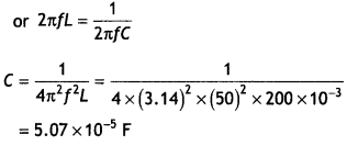
Question 11.
An ac voltage of 100V, 50 Hz is connected across a 20-ohm
resistor and 2 mH inductors in series.
Calculate (i) impedance of the
circuit, and
(ii) rms current in the circuit. (NCERT)
Answer:
Given, V
= 100 V, f = 50 Hz, R = 20 ohm, L = 2 mH = 2 × 10⁻³ H, Z = ?, lrms =
?
Using the relation
(a) Z =
\(\sqrt{(R)^{2}+\left(X_{L}\right)^{2}}=\sqrt{(R)^{2}+(2 \pi f L)^{2}}\)
Z =
\(\sqrt{(20)^{2}+\left(2 \times 3.14 \times 50 \times 2 \times
10^{-3}\right)^{2}}\)
Z = 20 ohm
(b) lrms= V/Z= 100/20 = 5 A
Question 12.
A light bulb is rated at 100 W for a 220 V supply. Find (a)
the resistance of the. bulb; (b) the peak voltage of the source; and (c) the rms
current through the bulb. (NCERT)
Answer:
(a) We are given P = 100 W and V
= 220 V.
The resistance of the bulb is
R =
\(\frac{V^{2}}{P}=\frac{(220)^{2}}{100}\) = 484 Ω
(b) The peak voltage of the source is
Vm = \(\sqrt{2}\)V = \(\sqrt{2}\) ×
220 = 311V
(c) Since P = I V, therefore l = P/V= 100/220 = 0.45 A
Question 13.
A pure Inductor of 25.0 mH is connected to a source of 220 V.
Find the inductive reactance and rms current in the circuit if the frequency of
the source is 50 Hz. (NCERT)
Answer:
The inductive reactance,
XL = 2 πf L = 2 × 3.14 × 50 × 25 × 10-3 Ω
= 7.85
ohm
The rms current in the circuit is
l = \(\frac{V}{X_{L}}=\frac{220}{7.85}\)
= 28 A
Question 14.
A 100 Ω resistor is connected to a 220 V, 50 Hz ac
supply.
(a) What is the rms value of current in the circuit?
(b) What is
the net power consumed over a full cycle? (NCERT)
Answer :
Given
urms = 220 V, f = 50 Hz, lrms = ?, P = ?
(a) lrms =
\(\frac{V_{\mathrm{rms}}}{R}=\frac{220}{100}\) = 2.2 A
(b) Power consumed over one cycle of ac P = Vrms × lrms = 220 × 2.2 = 484 W
Question 15.
(a) The peak voltage of an ac supply is 300 V. What is the
rms voltage?
(b) The rms value of current in an ac circuit is 10 A. What is
the peak current? (NCERT)
Answer:
(a) Vm = 300V,
Vrms =?
Using Vrms = \(\frac{V_{\mathrm{m}}}{\sqrt{2}}=\frac{300}{\sqrt{2}}\) = 212.16 V
(b) Using
lm = lrms × V2 = 10 ×
\(\sqrt{2}\) = 14.14 A
Question 16.
A 44 mH inductor is connected to 220 V, 50 Hz ac supply.
Determine the rms value of the current in the circuit. (NCERT)
Answer:
Given L = 44 mH = 44 × 10-3 H, Vrms = 220 V, f =
50Hz,lrms = ?
Using the relation
lrms =
\(\frac{V_{\text {rms }}}{x_{L}}=\frac{V_{\text {rms }}}{2 \pi f L}=\frac{220}{2
\times 3.14 \times 50 \times 44 \times 10^{-3}}\)
= 15.9 A
Question 17.
A coil of inductance 0.50 H and resistance 100 Ω is connected
to a 240 V, 50 Hz ac supply, (a) What is the maximum current in the coil? (b)
What Is the time lag between the voltage maximum and the current maximum?
(NCERT)
Answer:
Given L = 0.5 H, R = 100 Ω, Vrms = 240 V,
f=
50 Hz, ω = 2πf= 2 × 3.14 × 50 = 314 s-1 lm = ?
(a)
Now
Z = \(\sqrt{R^{2}+X_{L}^{2}}=\sqrt{(100)^{2}+(0.5 \times 314)^{2}}\)
Z
= 186.1 Ω
Therefore
l<sub>m</sub> = \(\frac{V_{m}}{Z}=\frac{\sqrt{2}
\times V_{\mathrm{rms}}}{Z}=\frac{\sqrt{2} \times 240}{186.1}\)
lm = 1.82 A
(b) Let Φ be the phase angle by which current lags emf, then
tan Φ =
\(\frac{X_{L}}{R}=\frac{0.5 \times 314}{100}\) = 1.571
Φ = 57.5° or Φ = 57.5
× π/180 rad
Therefore timw lag
t = \(\frac{\phi T}{2 \pi}=\frac{57.5 \times \pi}{180
\times 2 \pi \times 50}\) = 3.194 × 10⁻³ s
Question 18.
A coil of 0.01-henry Inductance and 1-ohm resistance is
connected to 200 volts, 50 Hz ac supply. Find the Impedance of the circuit and
time lag between max alternating voltage and current. (NCERT Exemplar)
Answer:
Given L = 0.01 henry, R = 1 ohm,
Vrms = 200V, f = 50Hz,
Z = ?, t = ?
We know that
XL = 2πfL = 2 × 3.14 × 50 × 0.01 =
3.14 ohm
Now
Z =
\(\sqrt{R^{2}+X_{\mathrm{L}}^{2}}=\sqrt{(3.14)^{2}+(1)^{2}}\) = 3.3 Ω
Also
tan Φ = \(\frac{X_{L}}{R}=\frac{3.14}{1}\)= 3.14
Or
Φ = tan-1
(3.14)
Or
Φ = 72° or 72 × π/180 rad
Now time lag Δt is
Δt =
\(\frac{\phi}{\omega}=\frac{72 \times \pi}{180 \times 2 \pi \times
50}=\frac{1}{250}\) s
Question 19.
An electrical device draws 2 kW power from AC mains (voltage
223 V (rms) = V50,000 V). The current differs (lags) in phase by Φ (tan Φ = –
3/4) as compared to voltage.
Find (i)R,
(ii) XC –
XL
(iii) lm
Another device has twice the values for R,
XC, XL. How are the answers affected? (NCERT Exemplar)
Answer:
Given P = 2 kW = 2000 W, Vrms = 223
= \(\sqrt{50,000}\)
V, tan Φ = – 3/4, R = ?,XC – XL = ?, lm = ?
(i)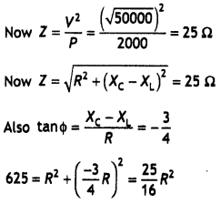
Solving for R we have
R = 20 ohm
(ii) Also XC – XL = (-3/4) R = – 15 Ω
Hence lrms
=\(\frac{V}{Z}=\frac{223}{25}\) = 9 A
(iii) lm = \(\sqrt{2}\) ×
lrms = 1.414 × 9 = 12.6 A
If R, XC, XL, are all doubled, tan Φ does not change. Therefore as Z is doubled, the current becomes halved.
Question 20.
An alternating voltage given by V = 140 sin 314 t is
connected across a pure resistor of 50 Ω. Find
(a) the frequency of the
source.
(b) the rms current through the resistor. (CBSEAI 2012)
Answer:
R = 50 Ω, f = ?, lrms = ?, Vm = 140 V
Comparing with V = Vm sin 2πft,
we have
2πft = 314 t
or
f
= 50 Hz
lrms = \(\frac{V_{r m s}}{R}=\frac{140}{50 \sqrt{2}}\) = 1.98 A
Question 21.
The figure shows a series LCR circuit with L = 5.0 H, C = 80
μF, R = 40 Ω connected to a variable frequency 240 V source. Calculate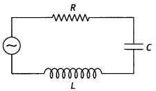
(a) The angular frequency of the source drives the circuit at resonance.
(b)
The current at the resonating frequency.
(C) The rms potential drops across
the capacitor at resonance. (CBSE Delhi 2012)
Answer:
Given L= 5.0 H, C=
80 μF , R = 40 Ω, Vrms = 240 V ωo = ?, lrms = ?,
VC = ?
(a)Angutar frequency at resonance
ω0 =
\(\sqrt{\frac{1}{L C}}=\sqrt{\frac{1}{5 \times 80 \times 10^{-6}}}\) = 50
s-1
(b)At resonance Z = R = 4O Ω
Now lrms =
\(\frac{V_{\mathrm{rms}}}{\mathrm{Z}}=\frac{240}{40}\) = 6 A
(C) VC = lrms × XC = 6 (50 × 80 × 10-6) = 1500 V
Question 22.
The figure shows a series LCR circuit connected to a variable
frequency 200 V source with L = 50 mH, C = 80 μF and R = 40 Ω.
Determine
(a) the source frequency which derives the circuit in resonance;
(b) the
quality factor (Q) of the circuit. (CBSEAI 2014C)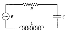
Answer:
(a) Given V = 200 V, L = 50 mH, C = 80 μF, R = 40 Ω
Source
frequency at resonance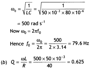
Question 23.
When an alternating voltage of 220 V is applied across a
device X, a current of 0.5 A flows through the circuit and is in phase with the
applied voltage. When the same voltage is applied across another device Y, the
same current again flows through it, but it leads the voltage by π/2 rattan.
(a) Name the devices X and Y.
(b) Calculate the current flowing In the
circuit when the same voltage Is applied across the series combination of the
two devices X and Y.
Answer:
(a) The two devices are resistor and
capacitor, respectively.
(b) Given l = 0.5 A, V = 220 V, XL = ?, R = ? , l = ?
Now
XC and R are equal and are given by
XC = R =
\(\frac{220}{0.5}\) = 440 Ω
Hence impedance of the circuit
Z =
\(\sqrt{R^{2}+X_{C}^{2}}=\sqrt{2(440)^{2}}\) = 622.25 Ω
Therefore current through the combination is
l =
\(\frac{V}{Z}=\frac{220}{622.25}\) = 0.354 A
Question 24.
In the following circuit, calculate (a) the capacitance of
the capacitor, if the power factor of the circuit is unity, (b) the Q-factor of
this circuit. What is the significance of the Q-factor in a.c. circuit? Given
the angular frequency of the a.c. source to be 100 s-1. Calculate the
average power dissipated in the circuit. (CBSE Delhi 2017C)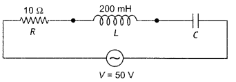
Answer:
(a) when the power factor is unity the circuit is in resonance,
therefore, we have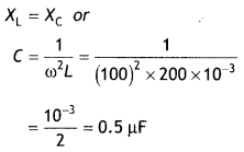
Quality factor determines the sharpness of tuning at resonance. More the Q
factor more the sharpness.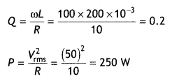
Question 25.
The figure below shows how the reactance of a capacitor
varies with frequency.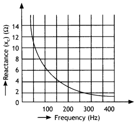
(a) Use the Information on the graph to calculate the value of capacity of the
capacitor.
(b) An inductor of inductance L has the same reactance as the
capacitor at 100 Hz. Find the value of L.
(c) Using the same axes, draw a
graph of reactance against frequency for the inductor.
(d) If this capacitor
and inductor were connected in series to a resistor of 10 Ω, what would be the
impedance of the combination at 300 Hz?
Answer:
(a) From the graph we find
that for a frequency of 100 Hz the capacitive reactance is 6 ohm,
therefore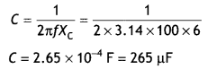
(b) Now given XL = XC at 100 Hz, therefore XL =
6 ohm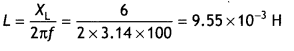
(c) The XL – f graph is as shown below.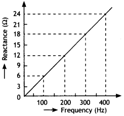
(d) For a frequency of 300 Hz, XL = 18 ohm and XC = 2
ohm. If resistance is 10 ohm then the impedance of the combination is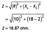
Question 26.
The given graphs (i) and (ii) represent the variation of the
opposition offered by the circuit element to the flow of alternating current,
with the frequency of the applied emf. Identify the circuit element
corresponding to each graph.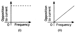
A circuit is set up by connecting L= 100 mH, C = 5 μf and R =100 Ω in series. An
alternating emf of (150 \(\sqrt{2}\)) volt, (500/π) Hz is applied across this
series combination. Calculate the impedance of the circuit. What is the average
power dissipated in (a) the resistor, (b) the capacitor, (c) the inductor, and
(d) the complete circuit?
Answer:
(a) Resistor and (b) Inductor
Given L
= 100 mH = 0.1 H, C = 5μF = 5 × 10⁻⁶F, R=100 Ω,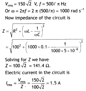
Average power dissipated in
(a) the resistor P = l2R =
(1.5)2 × 100 = 225 W
(b) power in inductor is zero.
(c) power
in capacitor is zero.
(d) the complete circuit is same as that in a
resistor.
Question 27.
The output voltage of an ideal transformer, connected to a
240 V ac mains, is 24 V. When this transformer is used to light a bulb with
rating 24 V, 24 W, calculate the current in the primary coil of the circuit.
Answer: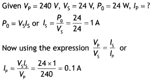
Question 28.
An ac generator consists of a coil of 50 turns and an area of
2.5 m2 rotating at an angular speed of 60 rads-1 in a
uniform magnetic field B = 0.2 tesla, between the two fixed pole pieces. The
resistance of the circuit including that of the coil is 500 ohm (a) Calculate
the maximum current drawn from the generator. (b) What is the flux when the
current is zero and (c) Would the generator work if the coil were stationary and
instead the pole pieces rotated together with the same speed as above? Give a
reason for your answer.
Answer:
Given n = 50, A = 2.5 m2, ω =
60 rads-1, B = 0.2 T, R = 500 ohm, l0 = ?
(a) The
maximum induced emf produced in the coil is
ε0 = nBAω = 50 × 0.2 ×
2.5 × 60 = 1500 V
Therefore maximum current in the circuit is
l0 =
\(\frac{\varepsilon_{0}}{R}=\frac{1500}{500}\) = 3 A
(b) The flux in this case is maximum and is given by Φ = nBA = 50 × 0.2 × 2.5 = 25 Wb
(c) Yes, for a generator to work there should be relative motion between the magnet and the coil.
Question 29.
The primary coil of an ideal step-up transformer has 100
turns and the transformation ratio is also 100. The input voltage and the powers
are 220 V and 1100 W respectively. Calculate:
(a) number of turns in the
secondary
(b) the current In the primary
(C) the voltage across the
secondary
(d) the current in the secondary
(e) power in the secondary
Answer:
Here, N = 100, Transformation ratio = 100
Vp = 220 V,
Pp = 1100W
(a) Number of turns in the secondary
Ns =
Np × Transformation ratio
= 100 × 100 = 10,000
(b) Current in the primary
lp =
\(\frac{P_{p}}{V_{p}}=\frac{1100}{220}\) = 5 A
(C) Voltage across the secondary Vs = Vp ×
transformation ratio
= 220 × 1oo = 22000 V
(d) Current in the secondary
ls = \(\frac{V_{p}
l_{p}}{V_{s}}=\frac{220 \times 5}{22000}\) = 0.05 A
(e) Power in the secondary = power in the primary (ideal transformer) = 1100 W
Question 30.
Calculate the current drawn by the primary of a transformer
which steps down 200 V to 20 V to operate a device of resistance 20 Q. Assume
the efficiency of the transformer to be 80 %.
Answer: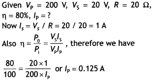
Question 31.
The primary of a transformer has 200 turns and the secondary
has 1000 turns. If the power output from the transformer at 1000 V is 9 kW,
calculate
(a) The primary voltage and
(b) The heat loss in the primary
coil if the resistance of the primary is 0.2 Ω and the efficiency of the
transformer is 90%.
Answer: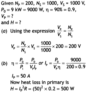
Question 32.
A power transmission line feeds input power at 2300 V to a
step-down transformer with its primary windings having 4000 turns. What should
be the number of turns in the secondary In order to get output power at 230 V?
(NCERT)
Answer: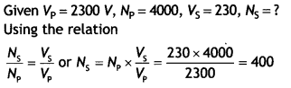
Question 33.
A small town with a demand of 800 kW of electric power at 220
V situated 15 km away from an electric plant generating power at 440 V The
resistance of the two wirelines carrying power is 0.5 Ω per km. The town gets
power from the line through a 4000 – 220 V step-down transformer at a
sub-station in the town.
(a) Estimate the line power loss in the form of
heat.
(b) How much power must the plant supply, assuming their negligible
power loss due to leakage?
(c) Characterise the step-up transformer at the
plant. (NCERT)
Answer:
Electric power required P = 800 kW = 800 ×
103 W
Voltage required V0 = 220 V
Distance of the power station
d = 15km = 15 × 103m
Resistance per kilometre = 0.5 ohm per km
Total resistance R = 0.5 × 2 ×
15 = 15 ohm
Input voltage Vi = 440 V
Primary voltage of transformer εp = 4000 V
Secondary voltage of
transformer εs = 220 V
(a) Rms value of current in the two wire
line
Therefore power loss along the line
= l2rmsR =
(200)2 × 15 = 600 kW
(b) Assuming negligible loss due to leakage Total power supply = power demand
of town + power loss along the line
P = 800 kW + 600 kW = 1400 kW
(c) Voltage drop on the line = 200 × 15 = 3000 V
Hence voltage at the
generation station
V= 4000 + 3000 = 7000 V
Therefore the step-up transformer at the plant is 440 V – 7000 V.
Question 34.
A 60 W load is connected to the secondary of a transformer
whose primary draws line voltage. If a current of 0.54 A flows in the load, what
is the current in the primary coil? Comment on the type of transformer being
used. (NCERT Exemplar)
Answer:
Given Ps = 60 W, ls =
0.54 A
We know that P=V I, therefore we have Vs =
Ps/ls = 60 /0.54 = 110 V
Therefore the transformer is a step-down transformer, whose transformation
ratio is 1/2
Therefore
lp = 1/2 × ls = 1/2 × 0.54 =
0.27 A