Electromagnetic Induction
Class 12th Physics Chapter Important Questions
Class 12 Physics Chapter 6 Important Extra Questions Electromagnetic Induction
Very Short Answer
Question 1.
A plot of magnetic flux (ϕ ) versus current (I) is shown in
the figure for two inductors A and B. Which of the two has larger value of self
inductance? (Delhi 2010)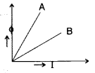
Answer:
Since ϕ = LI
∴ L = \(\frac{\phi}{I}\) =
slope
Slope of A is greater than slope of B
∴ Inductor A has larger value
of self inductance than inductor B.
Question 2.
Define self-inductance of a coil. Write its S.I. unit. (All
India 2010)
Answer:
Self induction is the property of a coil by virtue of
which it opposes the growth or decay of the current flowing through it.
S.I.
unit of self-inductance is henry (H).
Question 3.
Two bar magnets are quickly moved towards a metallic loop
connected across a capacitor ‘C’ as shown in the figure. Predict the polarity of
the capacitor. (All India 2013)
Answer:
When both magnets move towards loop, the A side
plate of cL capacitor will be positive while the lower plate B is negative,
making the induced current in a clockwise direction.

Question 4.
Predict the polarity of the capacitor when the two magnets are
quickly moved in the directions marked by arrows.
Answer:
Curerent in the coil will be anti-clockwise, when
seen from the left, therefore plate A will become + ve (positive) and plate B
will be negative.
Question 5.
Predict the directions of induced currents in metal rings 1
and 2 lying in the same plane where current I in the wire is increasing
steadily.
Answer:
In metal ring 1, the induced current flows in the
clockwise direction.
In metal ring 2, the induced current flows in the
anticlockwise direction.
Question 6.
Predict the direction of induced current in a metal ring when
the ring is moved towards a conductor is carrying current I in the direction
shown in the figure.
Answer:
Clockwise direction.
Question 7.
Predict the directions of induced current in metal rings 1 and
2 when current I in the wire is steadily decreasing?
Answer:
In metal ring 1, the induced current flows in
Anticlockwise direction.
In metal ring 2, the induced current flows in the
Clockwise direction.
Question 8.
A bar magnet is moved in the direction indicated by the arrow
between two coils PQ and CD. Predict the directions of induced current in each
coil. (All India 2012)
Answer:
By Lenz’s law, the ends of both the coils closer to the magnet behave
as south pole. Hence the current induced in both the coils will flow clockwise
when seen from the magnet side.
Question 9.
State Lenz’s law. (Comptt. All India 2012)
Answer:
Lenz’s law states that “the polarity of induced emf is such that it tends to
produce a current, which opposes the change in magnetic flux that induced
it”.
Question 10.
Predict the direction of the induced current in the
rectangular loop abed as it is moved into the region of a uniform magnetic field
\(\vec{B}\) directed normal to the plane of the loop. (Comptt. All India
2012)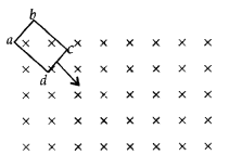
Answer:
The direction of the induced current in the given
rectangular loop is anti-clockwise, i.e., cbadc.
Question 11.
State Faraday’s law of electromagnetic induction. (Comptt.
All India 2012)
Answer:
Faraday’s law states that “The magnitude of emf
induced in a circuit is directly proportional to the rate of change of magnetic
flux linked with the circuit”. Mathematically, we can write,
\(e=-\frac{d
\phi}{d t}\) …where [dϕ is the small change in magnetic flux in small time
dt
Question 12.
How does the mutual inductance of a pair of coils change
when
(i) distance between the coils is increased and
(ii) number of turns
in the coils is increased (All India 2013)
Answer:
(i) Mutual inductance
decreases’, because flux linked with the secondary coil decreases.
(ii)
\(\mathrm{M}=\mu_{0} n_{1} n_{2} \mathrm{Al}\), so when n1 and
n2 increase, mutual inductance (M) increases.
Question 13.
A light metal disc on the top of an electromagnet is thrown
up as the current is switched on. Why? Give reason. (All India 2013)
Answer:
Because of Eddy Current
If the upper force of the core of the electromagnet acquires north polarity, then according to Lenz’s Law, the lower face of the disc will also acquire north polarity. Due to the force of repulsion between the lower face (N-pole) of the core of the electromagnet, the disc jumps upto a certain height.
Question 14.
The motion of copper plate is damped when it is allowed to
oscillate between the two poles of a magnet. What do the cause of this damping?
(All India 2013)
Answer:
The cause of this damping is eddy current.
Question 15.
The motion of copper plates is damped when it is allowed to
oscillate between the two poles of a magnet. If slots are cut in the plate, how
will the damping be affected? (All India 2013)
Answer:
Eddy current will
decrease due to which damping reduces.
Question 16.
How does the mutual inductance of a pair of coils change
when
(i) distance between the coils is decreased and
(ii) number of turns
in the coils is decreased? (All India 2013)
Answer:
(i) increases.
(ii)
decreases, because
\(\mathbf{M}=m_{0} n_{1} n_{2} \mathrm{Al}\)
where
[N1 and N2 are number of turns
Question 17.
Predict the polarity of the capacitor in the situation
described in the figure. (Comptt. Delhi 2013)
Answer:
When both magnets move towards loop, the A side
plate of cL capacitor will be positive while the lower plate B is negative,
making the induced current in a clockwise direction.
Question 18.
Two spherical bobs, one metallic and the other of glass, of
the same size are allowed to fall freely from the same height above the ground.
Which of the two would reach earlier and why? (Delhi 2014)
Answer:
Glass
bob would reach earlier because there would be a force acting upward due to eddy
currents on metallic bob being conducting, due to earth’s magnetic field. This
will slow down the metallic bob.
Question 19.
The electric current flowing in a wire in the direction from
B to A is decreasing. Find out the direction of the induced current in the
metallic loop kept above the wire as shown. (All India 2014)
Answer:
The direction of current in loop wire will be
clockwise.
Question 20.
A conducting loop is held above a current carrying figure.
Depict the direction of the current induced in the loop when the current in the
wire PQ is constantly increasing. (All India 2014)
Answer:
The current induced is in clockwise direction.
Question 21.
A conducting loop is held below a P current carrying wire PQ
as shown. Predict the direction of the induced current in the loop when the
current in the wire is constantly increasing. (All India 2014)
Answer:
The current induced is in anti clockwise
direction.
Question 22.
A metallic piece gets hot when surrounded by a coil carrying
high frequency alternating current. Why? (Comptt. Delhi 2014)
Answer:
Due
to the heating effect of eddy currents set up in the metallic piece.
Question 23.
Predict the polarity of the plate A of the capacitor, when a
magnet is moved ff’ towards it, as shown in the figure. (Comptt. All
India)
Answer:
The plate ’A’ has the positive polarity.
Question 24.
Define the term ‘self-inductance’ of a coil. Write its S.I.
Unit. (All India 2015)
Answer:
The self inductance of a coil numerically
equals to the induced emf produced in the coil, when the rate of change of
current in the coil is unity.![]()
(where L is the self inductance of the coil)
S.I. Unit :
Henry.
Question 25.
Name any two applications where eddy currents are used to
advantage. (Comptt. Delhi 2015 )
Answer:
Applications of Eddy currents
:
- Electromagnetic Damping
- Magnetic Breaking
- Induction Furnace
- Electric Power metres (any two)
Question 26.
A long straight current carrying wire passes normally through
the centre of a circular loop. If the current through the wire increases, will
there be an induced emf in the. loop? Justify. (Delhi 2015)
Answer:
No,As
the magnetic field due to current carrying wire will be in the plane of the
circular loop, so magnetic flux will remain zero.
Question 27.
Predict the polarity of the capacitor in the situation
described in the given diagram. (All India 2017)
Answer:
The polarity of plate ‘A’ of the given capacitor is positive,
while that of plate ‘B’ is negative.
Question 28.
A bar magnet is moved in the direction indicated by the arrow
between two coils PQ and CD. Predict the direction of the induced current in
each coil (All India 2017)
Answer:
Induced current flows from P to Q through ammeter;
while it flows
from D to C through ammeter.
Question 29.
What is the direction of induced currents in metal rings 1
and 2 when current I in the wire is increasing steadily? (All India
2017)
Answer:
The direction of induced current is clockwise in
metal ring ‘1’ and anti-clockwise in metal ring ‘2’.
Question 30.
In the figure given, mark the polarity of plates A and B of a
capacitor when the magnets are quickly moved towards the coil. (Comptt. All
India 2017)
Answer:
The polarity of plate is positive; 1 while that of plate B is
negative.
Question 31.
What is the function of a step-up transformer?
Answer:
The function of a step-up transformer is to step-up the
alternating voltage.
Question 32.
State Lenz’s law. (CBSE AI 2012C)
Answer:
It states that
the direction of induced emf is such that it opposes the cause of its
production.
Question 33.
How can the self-inductance of a given coil having ‘N’ number
of turns, area of cross-section of ‘A’ and length T be increased? (CBSE AI
2012C)
Answer:
By inserting a core of high permeability inside the
coil.
Question 34.
How does the mutual inductance of a pair of coils change
when
(a) the distance between the coils is increased and
(b) the number of
turns in the coils is increased? (CBSE AI 2013)
Answer:
(a) decreases
(b) increases.
Question 35.
The motion of the copper plate is damped when it is allowed to
oscillate between the two poles of a magnet. What is the cause of this damping?
(CBSE AI 2013)
Answer:
Production of eddy current.
Question 36.
Why is the core of a transformer laminated? (CBSE Delhi
2013C)
Answer:
To reduce the effects of eddy currents.
Question 37.
A metallic piece gets hot when surrounded by a coil carrying a
high-frequency alternating current. Why? (CBSE Delhi 2014C)
Answer:
Due to
the production of eddy current which generates heat.
Question 38.
Name any two applications where eddy currents are used to
advantage. (CBSE Delhi 2016C)
Answer:
- Electromagnetic damping
- Induction furnace.
Question 39.
A long straight current-carrying wire passes normally through
the centre of the circular loop. If the current through the wire increases, will
there be an induced emf in the loop? Justify. (CBSE Delhi 2017)
Answer:
Yes, as there will be a change in magnetic flux.
Question 40.
Predict the polarity of the capacitor in the situation
described below. (CBSE AI 2017)
Answer:
The upper plate will be positive with respect to the lower plate in
the capacitor.
Question 41.
In the figure given, mark the polarity of plates A and B of a
capacitor when the magnets are quickly moved towards the coil. (CBSE AI
2017C)
Answer:
Plate A will be positive with respect to plate B in the
capacitor.
Question 42.
A long straight current-carrying wire passes normally through
the centre of the circular loop. If the current through the wire increases, will
there be an induced emf in the loop? Justify. (CBSE Delhi 2017)
Answer:
Yes, as there will be a change in magnetic flux.
Question 43.
An air-cored solenoid has self-inductance 2.8 H. When the
core is removed, the self-inductance becomes 2 mH. What is the relative
permeability of the core used? (CBSE Delhi 2017C)
Answer:
μr =
2.8 / 2 × 10-3 = 1.4 × 10³
Question 44.
A choke and a bulb are in series to a dc source. The bulb
shines brightly. How does its brightness change when an iron core is inserted
inside the choke coil?
Answer:
There is no change in the brightness as the
inductive reactance is zero for dc.
Question 45.
Why does the acceleration of a magnet falling through a long
solenoid decrease?
Answer:
It decreases because of the opposing induced
emf produced in the soLenoid due to the rate of change of magnetic flux.
Question 46.
Why is the core of a transformer laminated?
Answer:
It
is done to reduce the effect of Eddy Currents.
Question 47.
A vertical metallic pole falls down through the plane of the
magnetic meridian. Will any emf be Induced between Its ends?
Answer:
No
emf will be induced because the pote neither intercepts the vertical component
nor the horizontal component of the earth’s magnetic field.
Question 48.
A magnet Is moved towards a coil and an electric charge is
induced in it. If the resistance of the coil is increased, how will the induced
charge change?
Answer:
On increasing the resistance of the colt, the
magnitude of induced charge decreases.
Question 49.
Can a transformer be used In a dc circuit?
Answer:
No,
because there is no change in magnetic flux.
Question 50.
Why does a metallic piece become very hot when it is
surrounded by a coil carrying high-frequency alternating current?
Answer:
The high-frequency coil induces eddy currents in the metallic piece. These eddy
currents produce heat hence the metalLic piece becomes hot.
Question 51.
The figure shows a horizontal solenoid PQ connected to a
battery and a switch. A copper ring R is placed on a frictionless track, the
axis of the ring being along the axis of the solenoid. What would happen to the
ring as the switch S is closed.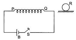
Answer:
The ring WilL be repelled due to opposing induced emf produced in
it.
Question 52.
An air-core solenoid is connected to an ac source and a bulb.
If an iron core Is inserted in the solenoid, how does the brightness of the bulb
change? Give reasons for your answer.
Answer:
Insertion of an iron core In
the solenoid increases its inductance. This in turn increases the value of
inductive reactance. This decreases the current and hence the brightness of the
bulb.
Question 53.
A magnet is moved in the direction indicated by an arrow
between two coils AB and CD as shown in the figure. Suggest the direction of
current in each coil,
Answer:
In coil AB induced current flows from A to B and in colt CD current
flows from C to D.
Question 54.
Predict the directions of induced currents in metal rings 1
and 2 lying in the same place where current I in the wire is increasing
steadily. (CBSE Delhi 2012)
Answer:
1 -clockwise, 2-anticlockwise.
Question 55.
The electric current flowing in a wire In the direction from
B to A is decreasing. Find out the direction of the induced current in the
metallic loop kept above the wire as shown. (CBSE AI 2014)
Answer:
Clockwise.
Question 56.
Predict the polarity of plate A of the capacitor, when a
magnet is moved towards it, as is shown In the figure. (CBSE AI 2014C)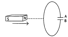
Answer:
Positive.
Question 57.
The figure below shows two positions of a loop PQR in a
perpendicular uniform magnetic field. In which position of the coil is there
induced emf?
Answer:
In position b.
Question 58.
If the self-inductance of an air-core inductor increases from
0.01 mH to 10 mH on introducing an iron core into it, what is the relative
permeability of the core used?
Answer:
We know that µ =
\(\frac{L}{L_{0}}=\frac{10}{0.01}\) = 1000
Short Answer Type
Question 1.
An induced current has no direction of its own, comment.
Answer:
Yes, it is perfectly correct to say that an induced current has no
fixed direction of its own. The direction of induced current depends upon the
change in magnetic flux because in accordance with Lenz’s law the induced
current always opposes the change in magnetic flux.
Question 2.
How are eddy currents produced? Mention two applications of
eddy currents?
Answer:
Eddy currents are the currents induced in the body
of a thick conductor when the magnetic flux linked with the conductor changes.
When a thick conductor is moved in a magnetic field, magnetic flux linked with
it changes. In situations like these, we can have induced currents that
circulate throughout the volume of a material.
Because their flow patterns resemble swirling eddies in a river, therefore they are called eddy currents.
- Electromagnetic braking, and
- Induction furnace.
Question 3.
Name and define the unit used for measuring the coefficient of
mutual inductance. State the relation of this unit with the units of magnetic
flux and electric current.
Answer:
In SI the unit of mutual inductance is
henry (H). Now from the expression
ε = – \(\frac{d \phi}{d t}\) = – M
\(\frac{d l}{d t}\)
we have M = ε l \(\frac{d l}{d t}\).
Let ε = 1 volt and dl/dt = 1 As-1, then
M = 1 volt/1
As-1 = 1 henry.
The mutual-inductance of a coil is said to be 1 henry if a rate of change of current of 1 ampere per sec in the neighbouring coil induces in at an emf of 1 volt.
Question 4.
What are eddy currents? Write any two applications of eddy
currents. (CBSE A! 2011)
Answer:
Eddy currents are the currents induced in
the body of a thick conductor when the magnetic flux linked with a bulk piece of
conductor changes.
- Dead Beat Galvanometer, and
- Induction furnace.
Question 5.
(a) Obtain the expression for the magnetic energy stored in a
solenoid in terms of the magnetic field B, area A and length l of the
solenoid.
(b) How is this magnetic energy per unit volume compared with the
electrostatic energy per unit volume stored in a parallel plate capacitor? (CBSE
Delhi 2011C)
Answer:
The magnetic field stored in a solenoid is given by
the expression U = – \(\frac{1}{2}\)Ll2.
But for a solenoid B = μ0nl
or
l = B / μ0 n
Substituting in the above expression we have
U = \(\frac{1}{2}\) ×
(μ0n2Al)\(\left(\frac{B}{\mu_{0} n}\right)^{2}\) as L =
μ0 n2 A l
U = \(\frac{1}{2}\)\(\frac{B^{2} A l}{\mu_{0}}\)
We know that the energy stored per unit volume in a parallel plate capacitor
is
UE = \(\frac{1}{2}\)ε0E2
It is clear that in both cases the energy stored per unit volume is proportional to the square of the field intensity.
Question 6.
Derive an expression for the self-inductance of a long
air-cored solenoid of length l and number of turns N. (Delhi 2008)
Answer:
Consider a long solenoid of length l and radius r with r << 1
and having n turns per unit length. If a current I flows through the coil, then
the magnetic field inside the coil is almost constant and is given by
B =
µ0nI
Magnetic flux linked with each turn = BA =
µ0nIA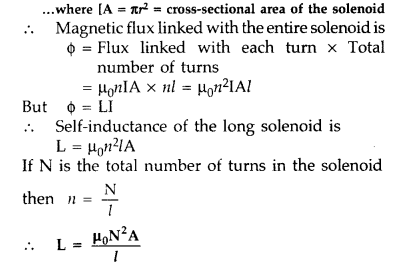
Question 7.
(i) When primary coil P is moved towards secondary coil S (as
shown in the figure) the galvanometer shows momentary deflection. What can be
done to have larger deflection in the galvanometer with the same
battery?
(ii) State the related law. (Delhi 2010)
Answer:
(i) To
have larger deflection in the galvanometer with the same battery, coil P has to
be moved faster towards S so that rate of change of magnetic flux is more.
(ii) The related law governing this phenomenon is Faraday’s second law of electromagnetic induction which states that induced emf is set up in a circuit when magnetic flux linked with it changes. The magnitude of induced emf is proportional to the rate of change of magnetic flux.
Question 8.
A coil Q is connected to low voltage bulb B and placed near
another coil P as shown in the figure. Give reasons to explain the following
observations :
(a) The bulb ‘B’ lights.
(b) Bulb gets dimmer if the coil
Q is moved towards left. (Delhi 2010)
Answer:
- The bulb B lights on account of emf induced in the coil Q due to mutual induction between P and Q.
- When coil Q is moved towards left, magnetic flux linked with Q decreases and may even reduce to zero at some distance. The emf induced may decrease and the bulb B gets dimmer.
Question 9.
Two identical loops, one of copper and the other of
aluminium, are rotated with the same angular speed in the same magnetic field.
Compare
(i) the induced emf and
(ii) the current produced in the two
coils. Justify your answer.(All India 2010)
Answer:
(i) Induced emf in a
coil is ε = NBAω sin ωt
As the angular speed is same, induced emf will also
be same in both the loops.
(ii) Current induced in a loop is
\(I=\frac{\varepsilon}{R}=\frac{\varepsilon A}{\rho l}\)
As the resistivity
of copper is lesser, more amount of current is induced in it.
Question 10.
A rectangular loop and a circular loop are moving out of a
uniform magnetic field to a field-free region with a constant velocity ‘v’ as
shown in the figure. Explain in which loop do you expect the induced emf to be
constant during the passage out of the field region. The magnetic field is
normal to the loops. (All India 2010)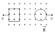
Answer:
In case of rectangular loop, induced emf will be
constant. It is because rate of change of the area of rectangular loop is
uniform whereas that of a circular loop is not constant.
Question 11.
A current is induced in coil C1 due to the motion
of current carrying coil C2.
(a) Write any two ways by which a large deflection can be
obtained in the galvanometer G.
(b) Suggest an alternative device to
demonstrate the induced current in place of a galvanometer .
Answer:
(a)
To obtain a large deflection, one or more of the following steps can be taken
:
- Use a rod made of soft iron inside the coil C2.
- Connect the coil to a powerful battery.
- Move the arrangement rapidly towards the test coil C1
(b) Replace the galvanometer by a small torch bulb.
Question 12.
A magnet is quickly moved in the direction indicated by an
arrow between two coils C1 and C2 as shown in the figure.
What will be the direction of induced current in each coil as seen from the
magnet? Justify your answer. (Delhi 2011)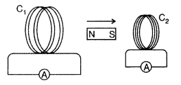
Answer:
When magnet moves in given direction, induced
current will be clockwise in both the coils as magnet is going away from
C1 and moving towards C2 making C1 as S pole
and C2 also as S pole according to Lenz rule. So C1 will
try to attract and C2 will try to repel the motion of magnet.
Question 13.
What are eddy currents? Write any two applications of eddy
currents. (All India 2011)
Answer:
(a) Eddy current : Due to change in
magnetic flux, if there is induced current in the volume (bulk) of the material,
it is called as eddy currents. It is a necessary evil in an arrangement as it
can be used in applications like electric brakes, induction furnaces and
dead-beat galvanometers and brings loss of energy with heat production etc.
(b) (i) As the arm RS of length l is moved with a uniform speed, there is a
change in area. It is given by dA = Idx = Ivdt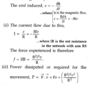
Question 14.
Define self-inductance of a coil. Show that magnetic energy
required to build up the current I in a coil of self inductance L is given by –
\(\frac{1}{2}\)I2. (Delhi 2011)
Answer:
The self-inductance of
a coil may be defined as the induced emf set up in the coil due to a unit rate
of change of current through it.
Let I be the current through the inductor L
at any instant t
The current rises at the rate dlldt, so the induced![]()
Work done against the induced emf in small time dt is![]()
Total work done in building up the current from 0 to I
in
This work done is stored as the magnetic field energy U in the inductor![]()
Question 15.
Define mutual inductance between two long coaxial solenoids.
Find out the expression for the mutual inductance of inner solenoid of length l
having the radius r1 and the number of turns n1 per unit
length due to the second outer solenoid of same length and n2 number
of turns per unit length. (Delhi 2011)
Answer:
Mutual induction is the
phenomenon of inducing emf in a coil due to the rate of change of current in a
nearby coil.
When a current I2 is set up through S2 (outer
solenoid), it in turn sets up a magnetic flux through S1. Let us
denote it by ϕ 1, The corresponding flux linkage with solenoid
S1 is,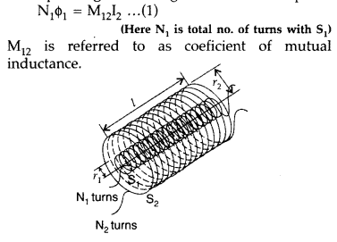
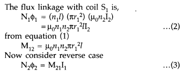
(Here N2 is total no. of turns with S2)
M21
is referred to as coefficient of mutual inductance of solenoid S2
with respect to solenoid S1.
Thus, flux linkage with solenoid
S2 is
Using equations (2) and (3), we get
M12 = M21 = M
If
a medium of relative permeability (it had been present the mutual inductance
would be![]()
Question 16.
A metallic rod of ‘L’ length is rotated with angular
frequency of ‘ω’ with one end hinged at the centre and the other end at the
circumference of a circular metallic ring of radius L, about an axis passing
through the centre and perpendicular to the plane of the ring. A constant and
uniform magnetic field B parallel to the axis is present everywhere. Deduce the
expression for the emf between the centre and the metallic ring. (Delhi
2012)
Answer:
The magnitude of the emf, generated across a length dr of
the rod, as it moves at right angles to the magnetic field, is given by
dε =
Bvdr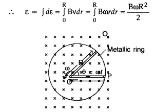
Alternatively, The potential difference across the resistor is equal to the
induced emf and equal B x .(rate of change of area of loop), If θ is the angle
between the rod and the radius of the circle at P at time t, the area of the
sector OPQ (as shown in the figure) is given by![]()
where [R is the radius of the circle]
Question 17.
Derive the expression for the self inductance of a long
solenoid of cross sectional area A and. length l, having n turns per unit
length.(Delhi 2012)
Answer:
Self-induction of a long solenoid : Consider a
long solenoid of length l and radius r with r << 1 and having n turns per
unit length. If a current I flows through the coil, then the magnetic field
inside the coil is almost constant and is given by![]()
Magnetic flux linked with each turn,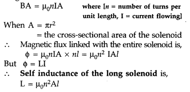
Question 18.
State Lenz’s Law.
A metallic rod held horizontally along
east-west direction, is allowed to fall under gravity. Will there be an emf
induced at its ends? Justify your answer. (Delhi 2012)
Answer:
Lenz’s law
states that “the polarity of induced emf is such that it tends to produce a
current, which oppose the change in magnetic flux that induced it”.
Yes there will be an emf induced as the horizontal component of field of earth, velocity of the motion of the rod and the length of the rod are all perpendicular to each other.
The magnetic flux due to vertical component of Earth’s magnetic field keeps on changing as the metallic rod falls down.
Question 19.
A rectangular loop PQMN with movable arm PQ of length 10 cm
and resistance 2 Ω is placed in a uniform magnetic field of 0.1 T acting
perpendicular to the plane of the loop as is shown in the figure. The
resistances of the arms MN, NP and MQ are negligible. Calculate the
(i) emf
induced in the arm PQ and
(ii) current induced in the loop when arm PQ is
moved with velocity 20 m/s. (Comptt. Delhi 2014)
Answer: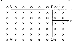
(i) emf induced![]()
(ii) Current in the loop,![]()
Question 20.
A rectangular loop PQMN with movable arm PQ of length 20 cm
and resistance 5 Ω is placed in a uniform magnetic field of 0.2 T acting
perpendicular to the plane of the loop as is shown in the figure.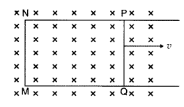
The resistances of the arms MN, NP and MQ are negligible.
Calculate the
(i) emf induced in the arm PQ and
(ii) current induced in
the loop when arm PQ is moved with velocity 15m/s (Comptt. Delhi 2014)
Answer:
Question 21.
State Lenz’s Law.
A metallic rod held horizontally along
the east-west direction is allowed to fall under gravity. Will there be an emf
induced at its ends? Justify your answer. (CBSE Delhi 2013)
Answer:
Lenz’s
law states that the polarity of the induced emf is such that it tends to oppose
the cause of its production.
Yes, as it will cut the horizontal component of the earth’s magnetic field.
Question 22.
Starting from the expression for the energy W =
1/2Ll2, stored in a solenoid of self-inductance L to build up the
current l, obtain the expression for the magnetic energy in terms of the
magnetic field B, area A and length l of the solenoid having n number of turns
per unit length. Hence show that the energy density is given by 8z/2m0. (CBSE
Delhi 2013C)
(i) The magnetic energy is
U = \(\frac{1}{2}\)LI2
= \(\frac{1}{2}\)L\(\left(\frac{B}{\mu_{0} n}\right)^{2}\) since B =
μ0nl
Now L = μ0n2 Al, therefore we have
UB =
\(\frac{1}{2}\)(μ0n2 Al)\(\left(\frac{B}{\mu_{0} n}\right)^{2}\) = \(\frac{1}{2
\mu_{0}} B^{2} A l\)
(ii) The magnetic energy per unit volume is
UB =
\(\frac{U_{B}}{V}=\frac{U_{B}}{A l}=\frac{B^{2}}{2 \mu_{0}}\)
Question 23.
Define mutual inductance. A pair of adjacent coils has a
mutual inductance of 1.5 H. If the current in one coil changes from 0 to 20 A in
0.5 s, what is the change of flux linkage with the other coil? (CBSE Delhi
2016)
Answer:
Mutual inductance is numerically equal to the magnetic flux
linked with a coil when the unit current passes through the neighbouring
coil.
Given M = 1.5 H, dl = 20 – 0 = 20 A,
dt = 0.5 s, Φ = ?
Φ = –
M\(\frac{d l}{d t}\)
or
Φ = – 1.5 × \(\frac{20}{0.5}\) = – 60 Wb
Question 24.
Explain the principle on which the metal detector is used at
airports for security reasons.
Answer:
The metal detectors used in airport
security checkpoints operate by detecting eddy currents induced in metallic
objects. The detector generates an alternating magnetic field. This induces eddy
currents in the conduction object carried through the detector. The eddy
currents in turn produce an alternating magnetic field. This field induces a
current in the detectors receiver coil.
Question 25.
A current is induced in coil C1, due to the motion
of current-carrying coil C2.
(i) Write any two ways by which a
large deflection can be obtained in the galvanometer G.
(ii) Suggest an
alternative device to demonstrate the induced current in place of a
galvanometer. (CBSE Delhi 2011)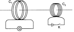
Answer:
(ii) The two ways are
(a) Passing a large current through coil
C2 and
(b) Moving coil C2 quickly towards the coil.
(ii) A magnetic compass can be placed at the centre of coil C1.
Whenever current will be induced it will show a deflection.
Question 26.
Consider a cube EFGHIJKL of side ‘a’ placed in a magnetic
field B acting perpendicular to the face FJKG as shown in the figure. Write
magnetic flux through the following faces (a) EFGH (b) EFJI (c) EILH (d)
FJKG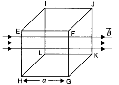
Answer:
The magnetic flux depends upon the angle (q) between the magnetic
field and area vector.
(a) Here θ = 90°, therefore magnetic flux Φ = BA cos θ
= BA cos 90° = 0
(b) Here θ = 90°, therefore magnetic flux Φ = BA cos θ = BA
cos 90° = 0
(c) Here θ = 180°, therefore magnetic flux Φ = BA cos 180° =
-BA
(d) Here θ = 0°, therefore magnetic flux Φ = BA cos 0° = BA
Question 27.
A metallic rod of ‘L’ length is rotated with an angular
frequency of ‘ω’ with one end hinged at the centre and the other end at the
circumference of a circular metallic ring of radius L, about an axis passing
through the centre and perpendicular to the plane of the ring. A constant and
uniform magnetic field B parallel to the axis is present everywhere. Deduce the
expression for the emf between the centre and the metallic ring. (CBSE Delhi
2012, 2013)
Answer:
Let the rod move from OP to OQ through a small sector
of angle θ.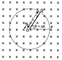
The
small area covered by the rod is
dA= πL2 × \(\frac{\theta}{2
\pi}=\frac{1}{2}\)L2θ
where L is the radius of the circle in which the rod rotates. Hence the
induced emf is
ε = \(\frac{d \phi}{d t}=\frac{d B A}{d t}=\frac{B d A}{d t}=B
\frac{d}{d t}\left[\frac{1}{2} L^{2} \theta\right]\)
ε = – \(\frac{1}{2}\)L2B\(\frac{d \theta}{d t}=\frac{1}{2}\)BωL2
Question 28.
A metallic rod of length l length is rotated with a frequency
ω, with one end hinged at the centre and the other end at the circumference of a
circular metallic ring of radius R = l, about an axis passing through the centre
and perpendicular to the plane of the ring. A constant and uniform magnetic
field B parallel to the axis is present everywhere. Deduce the expression for
the emf induced in the rod. If r is the resistance of the rod and the metallic
ring has negligible resistance, obtain the expression for the power generated.
(CBSE AI 2013C)
Answer:
For the first part refer above question.
The
power generated is given by
P = \(\frac{\varepsilon^{2}}{r}=\frac{B^{2}
\omega^{2} l^{4}}{2 r}\)
Question 29.
A rectangular loop PQMN with movable ‘ arm PQ of length 10 cm
and resistance 4 Ω is placed in a uniform magnetic field of 0.25 T acting
perpendicular to the plane of the loop as is shown in the figure. The
resistances of the arms MN, NP and MQare negligible.
Calculate the
(i) emf
induced in the arm PQand
(ii) current induced in the loop when arm PQ is
moved with velocity 20 m s-1. 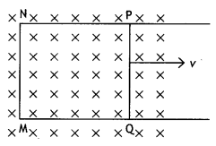
Answer:
Given L = 10 cm = 0.1 m, B = 0.25 T, v = 20 m s-1
(a) ε
= BLv = 0.25 × 0.1 × 20 = 0.5 V
(b) l = ε/R = 0.5/4 = 0.125 A
Question 30.
In the given diagram a coil B is connected to a low voltage
bulb L and placed parallel to another coil A as shown. Explain the following
observations
(i) Bulb lights, and
(ii) Bulb gets dimmer if coil B is moved
upwards.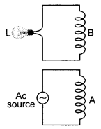
Answer:
(a) When ac is applied across coil A an induced emf is produced in
coil B due to mutual induction between the two coils. This makes the lamp light
up.
(b) When coil B is moved upwards the mutual induction and hence induced
emf in coil B decreases. This makes the lamp dimmer.
Question 31.
A metallic rod of length l is rotated at a constant angular
speed to, normal to a uniform magnetic field B. Derive an expression for the
current induced in the rod, if the resistance of the rod is R. (Delhi 2008)
Answer:
emf produced/induced across a small-section (dr) on the rod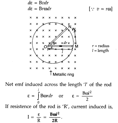
Question 32.
An inductor 200 mH, capacitor 500 µF, resistor 10 Ω are
connected in series with a 100 V variable frequency a.c. source. Calculate
the
(i) frequency at which the power factor of the circuit is unity
(ii)
current amplitude at this frequency
(iii) Q-factor (Delhi 2008)
Answer:
(i) Power factor will be unity at resonance,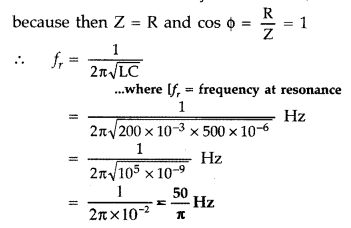
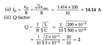
Question 33.
A coil of number of turns N, area A, is rotated at a constant
angular speed ω, in a uniform magnetic field B, and connected to a resistor R.
Deduce expressions for :
(i) Maximum emf induced in the coil.
(ii) Power
dissipation in the coil. (Delhi 2008)
Answer:
We know that induced
emf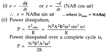
Question 34.
(a) Define self inductance. Write its S.I. units.
(b)
Derive an expression for self inductance of a long solenoid of length l,
cross-sectional area A having N number of turns. (Delhi 2009)
Answer:
(a)
Self-inductance of a coil
Since flux ϕ = LI![]()
where [L is coefficient of self-induction or self
inductance]
Self inductance is numerically equal to the magnetic flux linked
with the coil when unit current passes through it.
Its S.I. unit is
henry.
(b)
Consider a long solenoid of length l and radius r with r
<< 1 and having n turns per unit length. If a current I flows through the
coil, then the magnetic field inside the coil is almost constant and is given
by
B = µ0nI
Magnetic flux linked with each turn = BA =
µ0nIA
Question 35.
(i) State Faraday’s law of electromagnetic induction.
(ii)
A jet plane is travelling towards west at a speed of 1800 km/h. What is the
voltage difference developed between the ends of the wing having a span of 25 m,
if the Earth’s magnetic field at the location has a magnitude of 5 ×
10-4 T and the dip angle is 30°? (All India)
Answer:
(i) First
law : Whenever the magnetic flux linked with a closed circuit changes, an emf
(and hence a current) is induced in it which lasts only so long as the change in
flux is taking place. This phenomenon is called electromagnetic induction.
Second law : The magnitude of the induced emf is equal to the rate of change of
magnetic flux linked with the closed circuit.
Since v, l and B are to be perpendicular to get induce emf, the vertical
component alone will contribute to the induction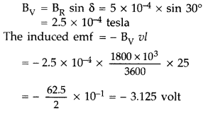
– ve sign signifies that the emf will oppose the change in
magnetic flux causing it.
Question 36.
State the law that gives the polarity of the induced emf.
(All India 2009)
Answer:
Law that gives the polarity of the induced emf is
:
Lenz’s law : “The direction of induced e.m.f. is such that it opposes the
cause which produces it. The polarity of induced e.m.f. can be determined by
Lenz’s law.”
Question 37.
A metallic rod of length ‘l’ is rotated with a frequency v
with one end hinged at the centre and the other end at the circumference of a
circular metallic ring of radius r, about an axis passing through the centre and
perpendicular to the plane of the ring. A constant uniform magnetic field B
parallel to the axis is present every where. Using Lorentz force, explain how
emf is induced between the centre and the metallic ring and hence obtain the
expression for it. (Delhi 2013)
Answer:
The magnitude of the emf,
generated across a length dr of the rod, as it moves at right angles to the
magnetic field, is given by
dε = Bvdr
Alternatively, The potential difference across the resistor is equal to the
induced emf and equal B x .(rate of change of area of loop), If θ is the angle
between the rod and the radius of the circle at P at time t, the area of the
sector OPQ (as shown in the figure) is given by![]()
where [R is the radius of the circle]
Question 38.
Starting from the expression for the energy w = \(\frac{1}{2}
\mathbf{L I}^{2}\), stored in a solenoid of self-inductance L to build up the
current I, obtain the expression for the magnetic energy in terms of the
magnetic field B, area A and length l of the solenoid having n number of turns
per unit length. Hence show that the energy density is given by
B2/2µ0. (Comptt. Delhi 2013)
Answer:
From these two equations, we get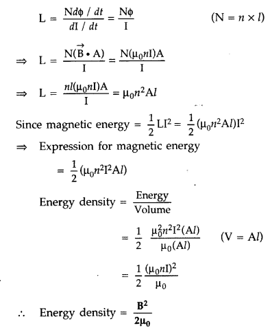
Question 39.
A metallic rod of length ‘l’ is rotated with a uniform
angular speed ω, with one end hinged at the centre and the other end at the
circumference of a circular metallic ring of radius R = l, about an axis passing
through the centre and perpendicular to the plane of the ring. A constant and
uniform magnetic field B parallel to the axis is present eveywhere. Deduce the
expression for the emf induced in the rod.
If r is the resistance of the rod
and the metallic ring has negligible resistance, obtain the expression for the
power generated. (Comptt. All India 2013)
Answer:
Are swept per rotation =
πR2 = πl2 [∵ R = l]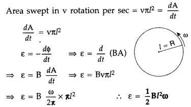
Question 40.
Write its SI unit for self-inductance of a coil. Derive the
expression for self-inductance of a long solenoid of cross-sectional area ‘A’,
length ‘l’ having ‘n’ turns per unit length. (Comptt. All India 2013)
Answer:
Coefficient of self induction.
Consider a coil L as shown in
Figure. Suppose a current I flows through the coil at any instant then magnetic
flux ϕ linked with the coil is directly proportional to the current passing
through it at that instant.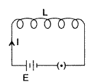
![]()
⇒ ϕ = LI where [L is called coefficient of self
induction]
If I = 1, then ϕ = L
Thus, self inductance of a coil is
numerically equal to the magnetic flux linked with the coil, when a unit current
flows through it.
The SI unit of self inductance is henry (H).
Expression for self-inductance : Consider a long solenoid of length Z and
cross-sectional area A having n turns per unit length.
The magnetic field due
to a current flowing in the solenoid is B = µ0nl
Total flux linked
with the solenoid is,![]()
where [nl is the total number of turns.]
Thus, the self
inductance is, \(\frac{\phi}{I}\)
If we fill the inside of the solenoid with a material of
relative permeability µr then
L =
µrµ0n2Al
Question 41.
A wheel with 8 metallic spokes each 50 cm long is rotated
with a speed of 120 rev/min in a plane normal to the horizontal component of the
Earth’s magnetic field. The Earth’s magnetic field at the place is 0.4 G and the
angle of dip is 60°. Calculate the emf induced between the axle and the rim of
the wheel. How will the value of emf be affected if the number of spokes were
increased? (All India 2013)
Answer:
If a rod length ‘l’ rotates with
angular speed ω in the uniform magnetic field B,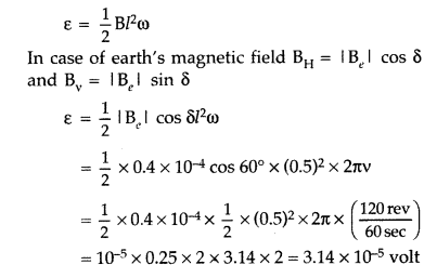
The induced emf will not change with the increase in the number of spokes.
Question 42.
Define the term ‘mutual inductance’ between the two
coils.
Obtain the expression for mutual inductance of a pair of long coaxial
solenoids each of length l and radii r1 and r2
(r2 >> r1). Total number of turns in the two
solenoids are N1 and N2 respectively. (All India 2013)
Answer:
(i) Mutual inductance. The mutual inductance of two coils is
numerically equal to the induced emf produced in one coil, when the rate of
change of current is unit in the other coil.
(ii)
(a) Lenz’s law (Direction) : “The direction of induced current in a circuit
is such as to oppose
the change that causes it. So \(e m f=-\frac{d \phi}{d
t}\)
When north pole of a magnet, for example, is brought near a coil, then
the nearer end of the coil will acquire north polarity and mechanical work will
be needed to cause the relative motion between the coil and the magnet. This
work, in fact, converts itself in the form of induced emf. Hence, the phenomenon
of electromagnetic induction is in accordance with the law of conservation of
energy.
(b) When a current I2 is set up through S2, it in turn
sets up a magnetic flux through S1. Let us denote it by
ϕ1. The corresponding flux linkage with solenoid S1
is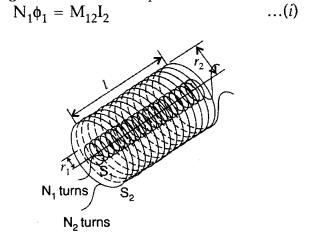
M12 is called the mutual inductance of solenoid S1 with
respect to solenoid S2.
The magnetic field due to the current
I2 in S2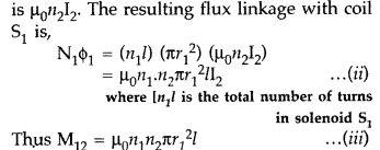
We now consider the reverse case :
A current I1, is passed through
the solenoid S1 and the flux linkage with coil S2
is,![]()
M21 is called the mutual inductance of the
solenoid S2 with respect to solenoid S1
The flux due to the current I1 in S1 can be assumed to
be confined solely inside S1 since the solenoid are very long. Thus,
flux linkage with solenoid S2 is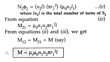
Question 43.
Define the term self-inductance of a solenoid. Obtain the
expression for the magnetic energy stored in an inductor of self-inductance L to
build up a current I through it. (All India 2014)
Answer:
Self-inductance:
emf is induced in a single isolated coil due to change of flux through the coil
by means of varying the current through the same coil. This phenomenon is called
self-induction. In this case, flux linkage through a coil of N turns is
proportional to the current through the coil and is expressed as![]()
where constant of proportionality L is called self-inductance
of the coil. It is also called the coefficient of self-induction of the coil.
When the current is varied, the flux linked with the coil also changes and an
emf is induced in the coil. Using the above equation the induced emf is given
by
Thus, the self-induced emf always opposes any change
(increase or decrease) of current in the coil. It is possible to calculate the
self-inductance for circuits with simple geometries. Let us calculate the
self-inductance of a long solenoid of cross-sectional area A and length Z,
having n turns per unit length. The magnetic field due to a current I flowing in
the solenoid is B = µ0nI (neglecting edge effects, as before). The
total flux linked with the solenoid is
If we fill the inside of the solenoid with a material of relative permeability
(e.g. soft iron, which has a high value of relative permiability), then L =
µrµ0n2Al
The self-inductance of the coil depends on its geometry and on the
permeability of the medium. The self-induced emf is also called the back emf as
it opposes any change in the current in a circuit. Physically, the
self-inductance plays the role of inertia. It is the electromagnetic analogue of
mass in mechanics. So, work needs to be done against the back emf (ε) in
establishing the current. This work done is stored as magnetic potential energy.
For the current I at an instant in a circuit, the rate of work done is![]()
If we ignore the resistive losses and consider only inductive
effect, then using![]()
Total amount of work done in establishing the current I
is,
Thus, the magnetic energy required to build up the current I
is,![]()
Question 44.
(a) A rod of length l is moved horizontally with a uniform
velocity ‘v’ in a direction perpendicular to its length through a region in
which a uniform magnetic field is acting vertically downward. Derive the
expression for the emf induced across the ends of the rod.
(b) How does one
understand this motional emf by invoking the Lorentz force acting on the free
charge carriers of the conductor? Explain. (All India 2014)
Answer:
(a)
Induced emf in rotating metallic rod: Suppose a rectangular loop LMNO is placed
in a uniform magnetic field B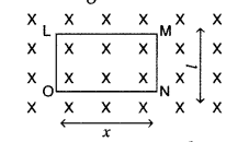
Suppose at any instant, length ON = x
Area of the loop
LMNO = lx
Flux through the loop, ϕ = Blx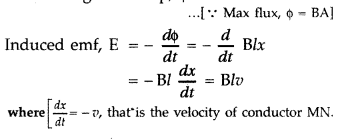
(b) The induced emf produced in a rod (l) moved with velocity (v) kept in a
magnetic field (perpendicular to the plane of length of the rod) is given by e =
BIv …(i)
This induced emf is called motional emf, by moving a conductor instead of varying the magnetic field; that is by changing the magnetic flux enclosed by the circuit.
We can explain motional emf by invoking the Lorentz force acting on the free
charge carriers of the conductor.
Lorentz force acting on charge q is![]()
The work done in moving, the charge through a distance is : W = qvBl
Since
the emf is the work done per unit![]()
This expression is the same as given in (i)
Question 45.
Derive the expression for the magnetic energy stored in a
solenoid in terms of magnetic field B, area A and length l of the solenoid
carrying a steady current I. How does this magnetic energy per unit volume
compare with the electrostatic energy density stored in a parallel plate
capacitor? (Comptt. Delhi 2015)
Answer:
Magnetic Energy in a
Solenoid,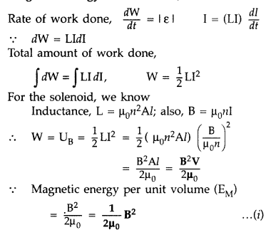
The electrostatic energy stored per unit volume for a parallel plate
capacitor,![]()
These two expressions are similiar in nature.
Question 46.
(i) Define mutual inductance.
(ii) A pair of adjacent
coils has a mutual inductance of 1.5 H. If the current in one coil changes from
0 to 20 A in 0.5 s, what is the change of flux linkage with the other coil?
(Delhi 2015)
Answer:
(i) Mutual inductance : Magnetic flux, linked with
the secondary coil due to the unit current flowing in the primary coil,
\(\phi_{2}=\mathrm{MI}_{1}\)
Therefore, induced emf associated with the
secondary coil, for a unit rate of change of current in the primary coil.
\(e_{2}=-\mathrm{M} \frac{d l_{1}}{d t}\)
[i.e. the phenomenon of production
of induced emf in one coil due to change in current in neighbouring coil]
(ii) Given : M = 1.5 H, I1 = 0, I2 = 20 A, ∆t = 0.5
sec, dϕ = ?
Change in flux (dϕ) = MdI = M(I2 – I1) =
1.5 (20 – 0) = 30 Weber
Question 47.
(a) Define self-inductance of a coil and hence write the
definition of ‘Henry’.
(b) Write any two factors each on which the following
depends :
(i) Self inductance of a coil.
(ii) mutual inductance of a pair
of coils. (Comptt. All India 2015)
Answer:
(a) The self-inductance (L) of
a coil equal the magnetic flux linked with it, when a unit current flows through
it.
One henry is the self inductance of a coil for which the magnetic flux,
linked with it, due to a current of 1A, flowing in it, equals one weber.
(b) (i) Self inductance of a coil depends on
- Its geometry (area and length of a coil.
- Number of turns
- Medium within the coil
(ii) Mutual inductance of a given pair of coils depends on
- Their geometries
- Their distance of separation
- Number of turns in each coil.
- Nature of medium in the intervening space.
Question 48.
(a) Define the term ‘self-inductance’ and write its S.I.
unit.
(b) Obtain the expression for the mutual inductance of two long
co-axial solenoids S1 and S2 wound one over the other,
each of length L and radii r1 and r2 and n1 and
n2 number of turns per unit length, when a current I is set up in the
outer solenoid S2. (Delhi 2017)
Answer:
(a) Self inductance of
a coil, equals the magnitude of the efrif induced in it, when the current in the
coil, is changing at a unit rate.
S.I. unit : henry
(b) Consider two long
solenoids S1 and S2 of same length l such that solenoid
S2 surrounds S1 completely.
Let a current
I2 flow through S2. This sets up a magnetic flux
ϕ1 through each turn of the coil S1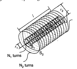
Total flux linked with S1,
N1ϕ1 = M12I2… (i)
Where
M12 is the mutual inductance between the two solenoids
Magnetic
field due to the current I2 and S2 is
µ0n2I2
Therefore, resulting flux linked with
S1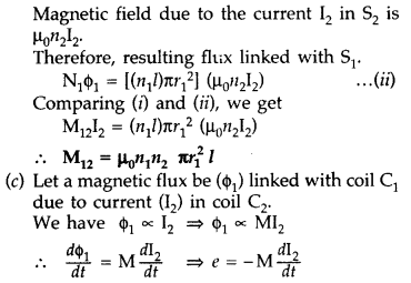
Question 49.
Define mutual inductance between a pair of coils. Derive an
expression for the mutual inductance of two long coaxial solenoids of same
length wound one over the other. (All India 2017)
Answer:
(a) Mutual
inductance of two coils is equal to the magnetic flux linked with one coil when
a unit current is passed in the other coil.
Hence, Mutual inductance is equal to the induced emf set up
in one coil when the rate of change of current flowing through the other coil is
unity.
S.I. unit : Henry, (Weber ampere-1) or (volt second
ampere-1)
(b) Consider two long solenoids S1 and S2 of same
length l such that solenoid S2 surrounds
S1 completely.
Let a current I2 flow through
S2. This sets up a magnetic flux ϕ1 through each turn of
the coil S1
Total flux linked with S1,
N1ϕ1 = M12I2… (i)
Where
M12 is the mutual inductance between the two solenoids
Magnetic
field due to the current I2 and S2 is
µ0n2I2
Therefore, resulting flux linked with
S1
Question 50.
Define self-inductance of a coil. Obtain the expression for
the energy stored in an inductor L connected across a source of emf. (All India
2017)
Answer:
(i) Definition of self-inductance :
(a) The
self-inductance (L) of a coil equal the magnetic flux linked with it, when a
unit current flows through it.
One henry is the self inductance of a coil for
which the magnetic flux, linked with it, due to a current of 1A, flowing in it,
equals one weber.
(ii) Expression for Magnetic Energy density in an ideal inductor :
Instantaneous induced emf in an inductor when current changes through it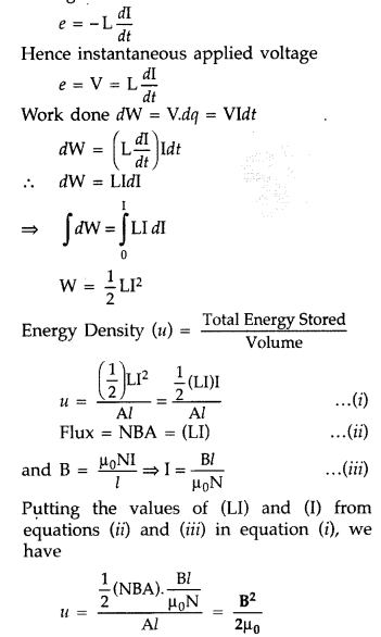
Question 51.
State Lenz’s law. Explain, by giving examples that Lenz’s law
is a consequence of conservation of energy. (Comptt. Delhi 2017)
Answer:
Lenz’s law states that “The polarity of induced emf is such that it tends to
produce a current which opposes the change in magnetic flux that produced
it.”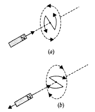
As shown in the diagram (a) given, when the north pole of a
bar magnet is pushed towards the close coil, the magnetic flux through the coil
increases and the current is induced in the coil in such a direction that it
opposes the increase in flux. This is possible when the induced current in the
coil is in the anticlockwise direction.
Similarly as shown in the diagram (b), just the opposite happens when the north pole is moved away from the coil.
In either case, it is the work done against the force of magnetic repulsion or attraction that gets ‘converted’ into the induced emf.
Question 52.
The current through two inductors of self-inductance 12 mH
and 30 mH is increasing with time at the same rate. Draw graphs showing the
variation of the
(a) emf induced with the rate of change of current in each
inductor
(b) energy stored in each inductor with the current flowing through
it.
Compare the energy stored in the coils, if the power dissipated in the
coils is the same. (Comptt. All India 2017)
Answer: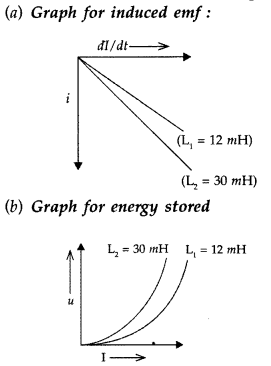
Comparison of energy stored :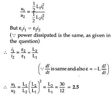
Question 53.
The current through two inductors of self-inductance 15 mH
and 25 mH is increasing with time at the same rate. Draw graphs showing the
variation of the
(a) emf induced with the rate of change of current
(b)
energy stored in each inductor with the current flowing through it.
Compare
the energy stored in the coils, if the power dissipated in the coils is the
same. (Comptt. All India 2017)
Answer:
Given L1 = 15 mH and
L2 = 25 mH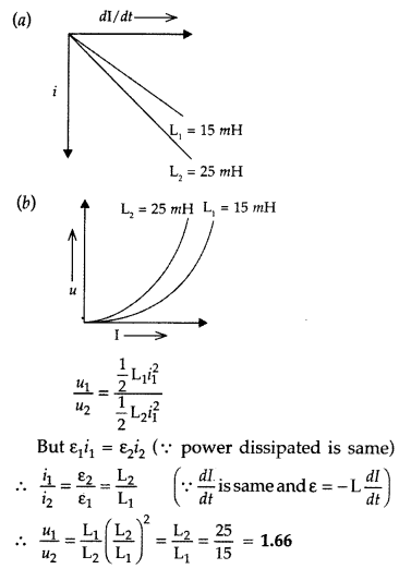
Question 54.
A horizontal straight wire of length L extending from east to
west is falling with speed v at right angles to the horizontal component of
Earth’s magnetic field B.
(a) Write the expression for the instantaneous
value of the emf induced in the wire.
Answer:
ε = BLv
(b) What is the direction of the emf?
Answer:
west to east
(c) Which end of the wire is at the higher potential?
Answer:
East.
Question 55.
Two concentric circular coils one of small radius
r1 and the other of large radius r2, such that
r1 << r2, are placed co-axially with centres
coinciding. Obtain the mutual inductance of the arrangement. (NCERT)
Answer:
Let a current l2 flow through the outer circular coil. The
field at the centre of the coil is B2 = \(\frac{\mu_{0} I_{2}}{2
r_{2}}\). Since the other coaxially placed coil has a very small radius, B2 may
be considered constant over its cross¬sectional area. Hence,
Φ =
πr1²B2 = \(\frac{\mu_{0} \pi r_{1}^{2} l_{2}}{2 r_{2}}\) =
M12l2
Thus M12 = \(\frac{\mu_{0} \pi r_{1}^{2}}{2 r_{2}}\)
But M12 = M21, therefore M12 = M21 = \(\frac{\mu_{0} \pi r_{1}^{2}}{2 r_{2}}\)
Note that we calculated M12 from an approximate value of Φ1 assuming the magnetic field B2 to be uniform over the area πr1². However, we can accept this value because r1 << r2.
Question 56.
Consider a magnet surrounded by a wire with an on/off switch
S (figure). If the switch is thrown from the off position (open circuit) to the
on position (closed circuit), will a current flow in the circuit? Explain.
(NCERT Exemplar)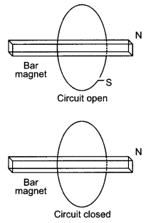
Answer:
There is no relative motion between the magnet and the coil. This
means that there is no change in magnetic flux, hence no electromotive force is
produced and hence no current will flow in the circuit.
Question 57.
A wire in the form of a tightly wound solenoid is connected
to a DC source and carries a current. If the coil is stretched so that there are
gaps between successive elements of the spiral coil, will the current increase
or decrease? Explain. (NCERT Exemplar)
Answer:
The current will increase.
As the wires are pulled apart the flux will leak through the gaps. Lenz’s law
demands that induced e.m.f. resist this decrease, which can be done by an
increase in current.
Question 58.
A solenoid is connected to a battery so that a steady current
flows through it. If an iron core is inserted into the solenoid, will the
current increase or decrease? Explain. (NCERT Exemplar)
Answer:
The
current will decrease. As the iron core is inserted in the solenoid, the
magnetic field increases and the flux increases. Lenz’s law implies that induced
e.m.f. should resist this increase, which can be achieved by a decrease in
current.
Long Answer Type
Question 1.
(a) What are eddy currents? Write their two applications.
(b) Figure shows a rectangular conducting loop PQSR in which arm RS of length
‘l’ is movable. The loop is kept in a uniform magnetic field ‘W directed
downward perpendicular to the plane of the loop. The arm RS is moved with a
uniform speed ‘v’.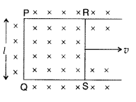
Deduce an expression for
(i) the emf induced across the
arm ‘RS’,
(ii) the external force required to move the arm, and
(iii) the
power dissipated as heat. (All India 2009)
Answer:
(a) Eddy current : Due
to change in magnetic flux, if there is induced current in the volume (bulk) of
the material, it is called as eddy currents. It is a necessary evil in an
arrangement as it can be used in applications like electric brakes, induction
furnaces and dead-beat galvanometers and brings loss of energy with heat
production etc.
(b) (i) As the arm RS of length l is moved with a uniform
speed, there is a change in area. It is given by dA = Idx = Ivdt
Question 2.
(a) State Lenz’s law. Give one example to illustrate this
law. “The Lenz’s law is a consequence of the principle of conservation of
energy.” Justify this statement.
(b) Deduce an expression for the mutual
inductance of two long coaxial solenoids but having different radii and
different number of turns. (All India 2009)
Answer:
(a) Lenz’s law
(Direction) : “The direction of induced current in a circuit is such as to
oppose
the change that causes it. So \(e m f=-\frac{d \phi}{d t}\)
When
north pole of a magnet, for example, is brought near a coil, then the nearer end
of the coil will acquire north polarity and mechanical work will be needed to
cause the relative motion between the coil and the magnet. This work, in fact,
converts itself in the form of induced emf. Hence, the phenomenon of
electromagnetic induction is in accordance with the law of conservation of
energy.
(b) When a current I2 is set up through S2, it in turn
sets up a magnetic flux through S1. Let us denote it by
ϕ1. The corresponding flux linkage with solenoid S1
is
M12 is called the mutual inductance of solenoid S1 with
respect to solenoid S2.
The magnetic field due to the current
I2 in S2
We now consider the reverse case :
A current I1, is passed through
the solenoid S1 and the flux linkage with coil S2
is,![]()
M21 is called the mutual inductance of the
solenoid S2 with respect to solenoid S1
The flux due to the current I1 in S1 can be assumed to
be confined solely inside S1 since the solenoid are very long. Thus,
flux linkage with solenoid S2 is
Question 3.
State Faraday’s law of electromagnetic induction. Figure
shows a rectangular conductor PQRS in which the conductor PQ is free to move in
a uniform magnetic field B perpendicular to the plane of the paper. The field
extends from x = 0 to x = b and is zero for x > b. Assume that only the arm
PQ possesses resistance r.
When the arm PQ is pulled outward from x = 0 to x
= 2b and is then moved backward to x = 0 with constant speed v, obtain the
expressions for the flux and the induced emf. Sketch the variations of these
quantities with distance 0 ≤ x ≤ 2b. (All India 2010)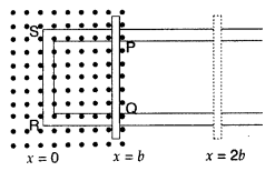
Answer:
Faraday’s law of electromagnetic induction: “The
magnitude of the induced emf in a circuit is equal to the time rate of change of
magnetic flux through the circuit”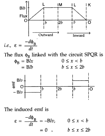
Question 4.
(a) Show that in an a.c. circuit containing a pure inductor,
the voltage is ahead of current by π/2 in phase.
(b) A horizontal straight
wire of length L extending from east to west is falling with speed v at right
angles to the horizontal component of Earth’s magnetic field B.
(i) Write the
expression for the instantaneous value of the emf induced in the wire.
(ii)
What is the direction of the emf?
(iii) Which end of the wire is at the
higher potential? (All India 2011)
Answer:
(a) Average power associated
with an inductor.
When a.c. is applied to an ideal inductor,current lags
behind the voltage in phase by \(\frac{\pi}{2}\) radian. So we can write the
instantaneous values of voltage and current as follows :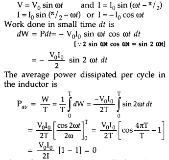
Thus the average power dissipated per cycle in an inductor is zero.
(b) (i)
The expression for the instantaneous value of the emf induced in the wire
is
ε = Blv
(ii) According to Fleming’s right hand rule, “the direction of
emf is from west to east”.
(iii) Eastern end of the wire is at the higher
electrical potential.
Question 5.
(a) Starting from the expression for the Lorentz magnetic
force acting on the free charge carriers of a conductor moving in a
perpendicular magnetic field, obtain the expression for the motional emf
induced.
(b) Hence deduce the expressions for the power delivered by the
source and the power dissipated as Joule heat. (Comptt. Delhi 2012)
Answer: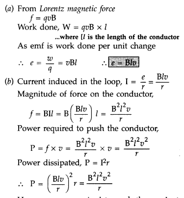
Hence, power required to push the conduct is same as the power dissipated.
Question 6.
(a) Describe a simple experiment (or activity) to show that
the polarity of emf induced in . a coil is always such that it tends to produce
a current which opposes the change of magnetic flux that produces it.
(b) The
current flowing through an inductor of self inductance L is continuously
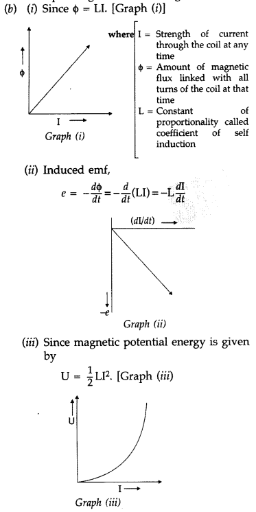
increasing. Plot a graph showing the variation of
(i) Magnetic flux versus
the current
(ii) Induced emf versus dI/dt
(iii) Magnetic potential energy
stored versus the current. (Delhi 2014)
Answer:
(a) Lenz’s law : According
to Lenz law, “the polarity of the induced emf is such that it opposes a change
in magnetic flux responsible for its production.”
Activity :
When the north pole of a bar magnet is pushed towards the coil, the amount of
magnetic flux linked with the coil increases. Current is induced in the coil
from a direction such that it opposes the increase in magnetic flux. This is
possible only when the current induced in the coil is in anti-clockwise
direction, with respect to an observer.
The magnetic movement ➝ M associated
with this induced emf has north polarity towards the north pole of the
approaching bar magnet.
Similarly, when the north pole of the bar magnet is moved away from the coil, the magnetic flux linked with the coil decreases. To counter this decrease in magnetic flux, current is induced in the coil in clockwise direction so that its south pole faces the receding north pole of the bar magnet. This would result in an attractive force which opposes the motion of the magnet and the corresponding decrease in magnetic flux.
Question 7.
A metallic rod of length l and resistance R is rotated with a
frequency v, with one end hinged at the centre and the other end at the
circumference of a circular metallic ring of radius l, about an axis passing
through the centre and perpendicular to the plane of the ring. A constant and
uniform magnetic field B parallel to the axis is present everywhere.
(a)
Derive the expression for the induced emf and the current in the rod.
(b) Due
to the presence of the current in the rod and of the magnetic field, find the
expression for the magnitude and direction of the force acting on this rod.
(c) Hence obtain the expression for the power required to rotate the rod.
(Comptt. All India 2012)
Answer: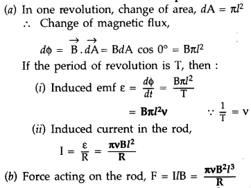
The external force required to rotate the rod opposes the Lorentz force acting
on the rod/ external force acts in the direction opposite to the Lorentz
force.
Power required to rotate the rod
Question 8.
(a) Define mutual inductance and write its S.I. units.
(b)
Derive an expression for the mutual inductance of two long co-axial solenoids of
same length wound one over the other.
(c) In an experiment, two coils
c1 and c2 are placed close to each other. Find out the
expression for the emf induced in the coil ct due to a change in the current
through the coil c2. (Delhi)
Answer:
(a) Mutual inductance of
two coils is equal to the magnetic flux linked with one coil when a unit current
is passed in the other coil.
Hence, Mutual inductance is equal to the induced emf set up
in one coil when the rate of change of current flowing through the other coil is
unity.
S.I. unit : Henry, (Weber ampere-1) or (volt second
ampere-1)
(b) Consider two long solenoids S1 and S2 of same
length l such that solenoid S2 surrounds
S1 completely.
Let a current I2 flow through
S2. This sets up a magnetic flux ϕ1 through each turn of
the coil S1
Total flux linked with S1,
N1ϕ1 = M12I2… (i)
Where
M12 is the mutual inductance between the two solenoids
Magnetic
field due to the current I2 and S2 is
µ0n2I2
Therefore, resulting flux linked with
S1
Question 9.
(a) State Lenz’s law. Use it to predict the polarity of the
capacitor in the situation given below :
(b) A jet plane is travelling towards west at a speed of 1800
km/h.
(i) Estimate voltage difference developed between the ends of the wing
having a span of 25 m if the earth’s magnetic field at the location has a
magnitude of 5 × 10⁻⁴ T and dip angle is 30°.
(ii) How will the
voltage developed be affected if the jet changes its direction from west to
north? (Comptt. All India)
Answer:
(a) Lenz’s law : It states that “the
direction of induced emf is such that it tends to produce a current which
opposes the change in magnetic flux producing it.”
Polarity of capacitor: Current induced in the coil will oppose the approach of the magnet, therefore, left face of the coil will act as N-pole and right face S-pole. For this the current in coil will be anticlockwise, as seen from left; and hence the plate ‘A’ of the capacitor will be positive and plate ‘B’ will be negative.
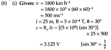
(ii) When the jet changes its direction from west to north, the voltage
developed will not be affected.
Question 10.
Define mutual inductance of a pair of coils and write on
which factors does it depend.
A square loop of side 20 cm is initially kept
30 cm away from a region of uniform magnetic field of 0.1 T as shown in the
figure. It is then moved towards the right with a velocity of 10 cm
s-1 till it goes out of the field.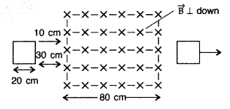
Plot a graph showing the variation of
(i) magnetic flux (ϕ) through the loop
with time (t)
(ii) induced emf (ε) in the loop with time t.
(iii) induced
current in the loop if it has resistance of 0.1 Ω. (Comptt. All India 2015)
Answer:
(a) Mutual inductance of two coils is equal to the magnetic flux
linked with one coil when a unit current is passed in the other coil.
Hence, Mutual inductance is equal to the induced emf set up
in one coil when the rate of change of current flowing through the other coil is
unity.
S.I. unit : Henry, (Weber ampere-1) or (volt second
ampere-1)
Factors:
- Separation between the coils
- Relative orientation of coils
- Number of turns in the coils
Given: Side of square loop (l) = 20 cm = 20 × 10-2 m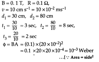
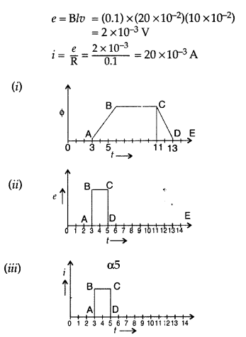
Question 11.
(a) Explain the meaning of the term mutual inductance.
Consider two concentric circular coils, one of radius r1 and the
other of radius r2 (r1 < r2) placed
coaxially with centres coinciding with each other. Obtain the expression for the
mutual inductance of the arrangement.
(b) A rectangular coil of area A,
having number of turns N is rotated at ‘f revolutions per second in a uniform
magnetic field B, the field being perpendicular to the coil. Prove that the
maximum emf induced in the coil is 2πf. (All India 2016)
Answer:
(a)
Mutual inductance of two coils is equal to the magnetic flux linked with one
coil when a unit current is passed in the other coil.
Hence, Mutual inductance is equal to the induced emf set up
in one coil when the rate of change of current flowing through the other coil is
unity.
S.I. unit : Henry, (Weber ampere-1) or (volt second
ampere-1)
(b) Consider two long solenoids S1 and S2 of same
length l such that solenoid S2 surrounds
S1 completely.
Let a current I2 flow through
S2. This sets up a magnetic flux ϕ1 through each turn of
the coil S1
Total flux linked with S1,
N1ϕ1 = M12I2… (i)
Where
M12 is the mutual inductance between the two solenoids
Magnetic
field due to the current I2 and S2 is
µ0n2I2
Therefore, resulting flux linked with
S1
(b) Let N = number of turns in the coil
A = Area of face of each turn
B
= Magnitude of the magnetic field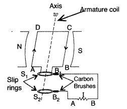
θ = Angle which normal to the coil makes with field
\(\overrightarrow{\mathrm{B}}\) at any instant t ω = Angular velocity with which
coil rotates The magnetic flux linked with the coil at any instant t will
be,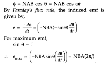
Hence Proved.
Question 12.
(a) A metallic rod of length l is moved perpendicular to its
length with velocity v in a magnetic field \(\overrightarrow{\mathrm{B}}\)
acting perpendicular to the plane in which rod moves. Derive the expression for
the induced emf.
(b) A wheel with 15 metallic spokes each 60 cm long, is
rotated at 360 rev/min in a place normal to the horizontal component of earth’s
magnetic field. The angle of dip at that place is 60°. If the emf induced
between rim of the wheel and the axle is 400 mV, calculate the horizontal
component of earth’s magnetic field at the place.
How will the induced emf
change, if the number of spokes is increased? (Comptt. All India 2016)
Answer:
(a) The magnitude of the emf, generated across a length dr of the
rod, as it moves at right angles to the magnetic field, is given by
dε =
Bvdr

Alternatively, The potential difference across the resistor is equal to the
induced emf and equal B x .(rate of change of area of loop), If θ is the angle
between the rod and the radius of the circle at P at time t, the area of the
sector OPQ (as shown in the figure) is given by![]()
where [R is the radius of the circle]
(b) Given : Number of spokes (n) = 15,
l = 60 cm = 60 × 10-2
m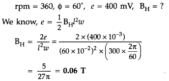
- There would be no effect on induced emf, if number of spokes is increased.
Question 13.
11 kW of electric power can be transmitted to a distant
station at (i) 220 V or (ii) 22,000 V. Which of the two modes of transmission
should be preferred and why? Support your answer with possible calculations.
Answer:
1. Consider that 11000 watt of energy has to be transmitted. First at
220 V and then at 22000 V. When the power is transmitted at 220 V then the
current flowing through the wires is 11000/220 = 50 A
2. When power is transmitted at 22000 V then the current through the wires is 11000 / 22000 = 0.5 A. If R is the resistance of the line wire then the energy dissipated in the two cases is 2500R joule per sec and 0.25R. joule per sec.
This shows that if energy is transmitted at low voltages there is more loss in energy than when it is transmitted at high voltages. Furthermore, if power is to be transmitted at low voltage then the resistance of the line wire should be low, as such thick wires will be required. To support these thick wires strong poles situated close to each other will be needed. This will increase the cost of transmission. But at high voltages, even thin wires will do.
Question 14.
A coil A is connected to a voltmeter V and the other coil B to
an alternating current source D. If a large copper sheet C is placed between the
two coils, how does the induced emf in coil A change due to current in coil B.
Justify your answer.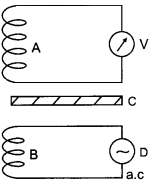
Answer:
In the absence of sheet C, an induced emf is set up in coil due to
mutual induction phenomenon when an alternating current is passed through coil
B.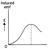
However, when induced copper sheet C is placed, eddy currents are set up in the
sheet due to a change in flux.
Thus, now coil A has a positive effect due to coil B and a negative effect due to eddy currents in C. Consequently, the flux of coil A and hence the induced emf in coil A is decreased, i.e. the reading of voltmeter V is reduced.
Question 15.
A bar magnet is dropped so that it falls vertically through
coil C. The graph obtained for the voltage produced across the coil versus time
is as shown in figure (b).
(i) Explain the shape of the graph and
(ii) why
is the negative peak longer than the positive peak?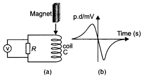
Answer:
(a) As the magnet approaches the coil, an emf is induced in it. As
the magnet approaches the coil the magnetic flux linked with the coil increases.
As a result the induced emf increases. When the magnet enters the coil, the
change in magnetic flux linked with the coil begins to decrease and becomes zero
when the magnet is completely inside the coil. This starts decreasing the emf
and makes it zero.
When the magnet comes out of the coil the direction of induced emf changes direction and begins to increase in the opposite direction. When the magnet moves far away from the coil the induced emf becomes zero.
As the magnet comes out of the coil with a speed greater than the speed at which it approaches the coil, therefore the induced emf is more in the second case. Hence the longer negative peak.
Question 16.
(a) State Lenz’s law: Using this law indicate the direction of
the current in a closed loop when a bar magnet with the North Pole is brought
close to it. Explain briefly how the direction of the current predicted wrongly
results in the violation of the law of conservation of energy.
(b) A
rectangular loop and circular loop are moving out of a uniform magnetic field
region with a constant velocity v as shown in the figure. In which loop do you
expect the induced emf to be constant during the passage out of the field
region? The field is normal to the loops. (CBSE AI 2011C)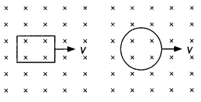
Answer:
(a) Lenz’s law states that the direction of the induced emf is such
that it opposes the cause of its production. When the north pole of the magnet
is brought near the coil, the upper end of the coil will acquire north polarity
so as to oppose the approaching North Pole (by repelling). This means that the
direction of current must be anticlockwise as seen from the side of the
magnet.
If the current is wrongly predicted as clockwise, then the upper face will acquire south polarity which will attract the North Pole. This means the current is being produced without doing any work. This leads to the violation of the law of conservation of energy.
(b) It is expected that the induced emf will be constant in the rectangular coil. In the case of the rectangular coil, when pulled out of the magnetic field, the rate of change of magnetic flux will be constant because the rate of change of area is constant. This is not so in the case of the circular coil.
Question 17.
The current through two inductors of self-inductance 15 mH and
25 mH is increasing with time at the same rate. Draw graphs showing the
variation of the
(a) emf induced with the rate of change of current
(b)
energy stored in each inductor with the current flowing through it. Compare the
energy stored in the coils, if the power dissipated in the coils is the same.
(CBSE AI 2017C)
Answer:
Given L1 = 15 mH, L2 = 25
mH.
(a) The emf induced across an inductor is given by the expression ε = –
L\(\frac{d i}{d t}\) since di/dt is the same for both coils therefore induced
emf will depend upon the value of inductance. Hence the graphs are as
shown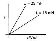
(b) The energy stored in an inductor is given by U =
\(\frac{1}{2}\)Ll2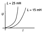
(c) The power dissipated P = l2XL
or
l2 =
Pl XL and U = \(\frac{1}{2}\)Ll<sup>1</sup> = \(\frac{1}{2} \frac{L
P}{X_{L}}=\frac{1}{2} \frac{P L}{\omega L}=\frac{P}{2 \omega}\)
Since power dissipated is same and co is also same therefore energy stored in the coils will also be the same.
Question 18.
A rectangular frame of wire is placed in a uniform magnetic
field directed outwards, normal to the paper. AB is connected to a spring which
is stretched to AB and then released at time t = 0. Explain qualitatively how
induced e.m.f. in the coil would vary with time. (Neglect damping of
oscillations of spring) (CBSE AI 2018C)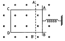
Answer:
As the spring is released AB is pulled out of the field. This
increases the area of the loop inside the magnetic field. This increases flux
and hence an induced emf is produced. The portion AB does not stop at Ab but
moves outwards. Now the spring will push AB inwards. This will decrease the area
of the loop thereby decreasing the induced emf. This continues and hence the emf
increases and decreases periodically.
Question 19.
Define mutual inductance between a pair of coils. Derive an
expression for the mutual inductance of two long coaxial solenoids of the same
length wound one over the other. (CBSE AI 2017)
Answer:
The mutual
inductance of two coils is numerically equal to the magnetic flux linked with
one coil when a unit current flows through the neighbouring coil.
As shown in the figure consider two long co-axial solenoids S1 and
S2 with S2 wound over S1.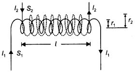
Let l = length of each solenoid r1, r2 = radii of the two
solenoids
A = πr1² = area of cross-section of inner solenoid
S1
N1, N2 = number of turns in the two
solenoids First we pass a time-varying current l2 through
S2. The magnet field set up inside S2 due to l2
is
B2 = μo n2 l2
where n2 = N2/l = the number of turns per unit length of S2.
Total magnetic flux linked with the inner solenoid S1
is
Φ1 = B2AN1 = μ0 n2
l2 × AN1
Mutual inductance of coil 1 with respect to coil 2 is
M12 =
\(\frac{\phi_{1}}{l_{2}}\) = μ0n2AN1 = \(\frac{\mu_{0} A N_{1}
N_{2}}{l}=\frac{\mu_{0} \pi r^{2} N_{1} N_{2}}{l}\)
The mutual inductance of any two coils is always proportional to the product N1 N2 of their number of turns. This is termed the reciprocity theorem.
Question 20.
Define mutual inductance and write its SI unit.
A square
loop of side ‘a’ carrying a current l2 is kept at distance x from an
infinitely long straight wire carrying a current l1 as shown in the figure.
Obtain the expression for the resultant force acting on the loop. (CBSE Delhi
2019)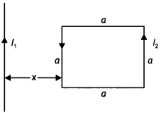
Answer:
(a) Mutual inductance equals the magnetic flux associated with a coil
when unit current flows in its neighbouring coil. (b) Force per unit length
between two parallel straight conductors
\(\frac{F}{L}=\frac{\mu_{o} I_{1}
I_{2}}{2 \pi r}\)
Force on the part of the loop which is parallel to infinite straight wire and at a distance x from it F = \(\frac{\mu_{o} l_{1} l_{2} a}{2 \pi x}\)(away from the infinitely 2KX long wire)
Force on the part of the loop which is at a distance (x + a) from it
F2 = \(\frac{\mu_{0} I_{1} I_{2} a}{2 \pi(x+a)}\) (towards the
infinite long wire)
Net force F = F1 – F2
F = \(\frac{\mu_{o} l_{1}
l_{2} a^{2}}{2 \pi(x+a)}\) (away from the infinite straight line)
Question 21.
What are the possible causes of energy loss in a transformer?
How are these minimised?
Answer:
The possible causes of energy losses in
transformers are:
(a) Flux leakage: There is always some flux leakage. It can
be reduced by winding the primary and secondary coils one over the other.
(b)
Copper: The copper wires used for the windings have some resistance and hence
some energy is lost due to heat produced in the wire. It can be minimised by
taking thick wire.
(c) Eddy currents: The alternating magnetic flux induces
eddy currents in the iron core, which results in loss of electrical energy. To
minimise it we use a laminated iron core.
(d) Hysteresis loss: As the
magnetisation cycle of the iron core is repeated again and again some loss of
energy takes place due to magnetic hysteresis. To minimise it we prefer a soft
iron core for which hysteresis loss is less.
Question 22.
Discuss how Faraday’s law of e.m.f induction is applied in an
ac generator for converting mechanical energy into electrical energy. Draw
graphs to show the ’phase relationship’ between the instantaneous
(a)
magnetic flux (Φ) linked with the coil and
(b) induced emf (ε) in the coil.
(CBSE Delhi 2016C)
Answer:
In an ac generator, the change in magnetic flux
is brought about by rotating the coil in a magnetic field. According to
Faraday’s law, induced emf is set up in the coil on changing the magnetic flux
linked with it. Hence mechanical energy, which is supplied to rotate the coil,
gets converted into electrical energy.
Let the coil be rotated with a constant angular speed, co, the angle 0 between magnetic field 8, and area vector A of the coil at any instant is θ = ωt
Therefore magnetic flux at any instant is Φ = BA cos ωt
From Faraday’s law, induced emf is
ε = – n\(\frac{d \phi}{d t}\) =
-nBA\(\frac{d}{d t}\)cos ωt
ε = nBAa sin ωt
Magnetic flux is given by Φ = BA cos ωt, therefore the graph will be a cosine
curve as shown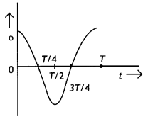
The induced emf is given by ε = nBA sin ωt, therefore the graph will be a sine
curve as shown.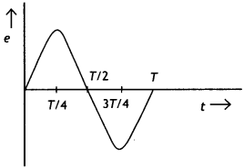
Question 23.
(a) Define self-inductance of a coil. Obtain an expression for
the energy stored in a solenoid of self-inductance ‘L’ when the current through
it grows from zero to l.
(b) A square loop MNOP of the side 20 cm is placed
horizontally in a uniform magnetic field acting vertically downwards as shown in
the figure. The loop is pulled with a constant velocity of 20 cm s-1
till it goes out of the field.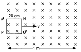
(c) Depict the direction of the induced current in the loop as it goes out of
the field. For how long would the current in the loop persist?
(d) Plot a
graph showing the variation of magnetic flux and induced emf as a function of
time. (CBSE AI 2015)
Answer:
(a) Let i be the current at some instant
through a pure inductor. If di / dt is the rate of change of current through the
inductor then the voltage between the terminals of the inductor at this instant
is
V=L di / dt
Therefore instantaneous power in the inductor is
P = Vab i = Li
\(\frac{d i}{d t}\)
The energy dU supplied to the inductor during an infinitesimal time interval
dt is
dU = P dt, so dU = Li di
The total amount of energy supplied while the current increases from zero to
a final value l is
U = L ∫o1 i di = \(\frac{1}{2}\)L
l2
(b) (i) Direction of induced current – clockwise (MNOP), the duration of
induced current is 1s.
(ii) The graph is as shown.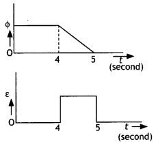
Question 24.
(a) Define mutual inductance and write its SI units.
Answer:
The mutual inductance of two coils is numerically equal to the
magnetic flux linked with one coil when a unit current flows through the
neighbouring coil. It is measured in henry.
(b) Derive an expression for the mutual inductance of two long co-axial
solenoids of the same length wound one over the other.
Answer:
The mutual
inductance of two coils is numerically equal to the magnetic flux linked with
one coil when a unit current flows through the neighbouring coil.
As shown in the figure consider two long co-axial solenoids S1 and
S2 with S2 wound over S1.
Let l = length of each solenoid r1, r2 = radii of the two
solenoids
A = πr1² = area of cross-section of inner solenoid
S1
N1, N2 = number of turns in the two
solenoids First we pass a time-varying current l2 through
S2. The magnet field set up inside S2 due to l2
is
B2 = μo n2 l2
where n2 = N2/l = the number of turns per unit length of S2.
Total magnetic flux linked with the inner solenoid S1
is
Φ1 = B2AN1 = μo n2
l2 × AN1
Mutual inductance of coil 1 with respect to coil 2 is
M12 =
\(\frac{\phi_{1}}{l_{2}}\) = μ0n2AN1 = \(\frac{\mu_{0} A N_{1}
N_{2}}{l}=\frac{\mu_{0} \pi r^{2} N_{1} N_{2}}{l}\)
The mutual inductance of any two coils is always proportional to the product N1 N2 of their number of turns. This is termed the reciprocity theorem.
(c) In an experiment, two coils c1 and c2 are placed
close to each other. Find out the expression for the emf induced in the coil
c1 due to a change in the current through the coil c2.
(CBSE Delhi 2015)
Answer:
Consider the experimental set up as
shown.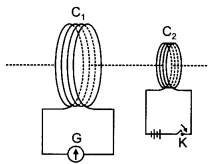
When the key K is pressed in coil C1 a magnetic flux linked with
C2 changes.
The magnetic flux linked with coil C2 is given by
f2
= M l1 where M is the mutual inductance between the two coils.
But by Faraday’s flux rule we have
ε2 = – \(\frac{d \phi}{d
t}\) therefore we have
ε2 = – \(\frac{d M l_{1}}{d t}\) = – M
\(\frac{d l_{1}}{d t}\)
Question 25.
(a) When a bar magnet is pushed towards (or away) from the
coil connected to a galvanometer, the pointer in the galvanometer deflects.
Identify the phenomenon causing this deflection and write the factors on which
the amount and direction of the deflection depend. State the laws describing
this phenomenon.
(b) Sketch the change In flux, emf and force when a
conducting rod PQ of resistance R and length I moves freely to and fro between A
and C with speed v on a rectangular conductor placed in the uniform magnetic
field as shown in the figure. (CBSE AI 2016)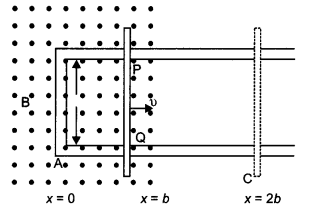
Answer:
(a) Phenomenon: electromagnetic induction
Factors:
- Strength of the magnetic field of the magnet
- speed of motion of bar magnet.
Direction depends upon
- the motion of magnet whether inward or outward
- the direction of the north/south pole.
Law: The magnitude of the induced emf in a circuit is equal to the time rate of change of magnetic flux through the circuit.
(b) The sketch is as shown below.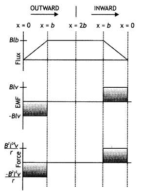
Question 26.
What is induced emf? Write Faraday’s laws of electromagnetic
induction. Express it mathematically. A conducting rod of length ‘L’ with one
end pivoted is rotated with a uniform angular velocity ‘ω’ in a vertical plane,
normal to a uniform magnetic field ‘B’. Deduce an expression for the emf induced
in this rod.
Answer:
It is the emf induced when the magnetic flux linked
with a coil changes.
Faraday put forward the following laws called Faraday’s laws of electromagnetic induction.
- Law 1. Whenever the magnetic flux linked with a coil changes an induced emf is produced.
- Law 2. The induced emf lasts as long as the change in magnetic flux continues.
The expression for induced emf in rotating rod: Let the rod move from OP to
OQ through a small sector of angle θ.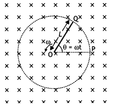
The
small area covered by the rod is
dA = πL2 × \(\frac{\theta}{2
\pi}=\frac{1}{2}\)L2θ
where L is the radius of the circle in which the rod rotates. Hence the
induced emf is
ε = \(\frac{d \phi}{d t}=\frac{d B A}{d t}=\frac{B d A}{d t}=B
\frac{d}{d t}\left[\frac{1}{2} L^{2} \theta\right]\)
Or
ε = \(\frac{1}{2}
L^{2} B \frac{d \theta}{d t}=\frac{1}{2}\)BωL2
Question 15.
How is the mutual inductance of a pair of coils affected
when:
(a) the separation between the coils is increased?
Answer:
When
the separation between the two coils is increased the mutual inductance
decreases. It is because the flux linked with the secondary due to a current in
the primary decreases.
(b) the number of turns of each coil is increased?
Answer:
When the
number of turns of each coil is increased the mutual inductance increases
because M12 (= M21) ∝ N1N2,
i.e. mutual inductance is directly proportional to the number of turns. The linkage of flux increases with an increase in the number of turns in the coils.
(c) a thin iron sheet is placed between the two coils, other factors
remaining the same? Explain your answer in each case.
Answer:
When a thin
iron sheet is placed between the coils the permeability of the medium between
the coil increases. As mutual inductance is directly proportional to the
permeability, therefore the mutual inductance increases.
Question 27.
A rectangular coil of area A, having a number of turns N, is
rotated at f revolutions per second in a uniform magnetic field B, the field
being perpendicular to the coil. Prove that the maximum emf induced in the coil
is 2π f N B A.
Answer:
Consider an armature of the ac generator having n
turns and placed in a uniform magnetic field B.
Suppose at any instant t the normal to the plane of the coil makes an angle 0 with the direction of the magnetic field. If ro is the uniform angular velocity with which, the coil rotates then θ = ωt.
The flux through the loop equals its area A multiplied by B⊥ = Bcos θ, the component of magnetic field B perpendicular to the area, hence
Φ = n B A cos Φ = n B A cos ω t …(1)
where is the number of turns in the
armature?
By Faraday’s flux rule,
ε = – \(\frac{d \phi}{d t}=-\frac{d}{d t}\) n B A
cos ω t
= – n B A \(\frac{d}{d \phi}\)cos ω t = – n B A (- ω sin ω t)
….(2)
Or
ε = n B A ω sin ω t
The induced emf is maximum when sin ωt = maximum = 1, therefore the maximum
induced emf is given by
ε0 = n B A ω sin ω t …(3)
Since ω = 2πf, therefore equation (3) becomes ε0 = 2πf nBA
Question 28.
State Lenz’s law. Explain by giving examples that Lenz’s law
is a consequence of the law of conservation of energy. (CBSE Delhi 2017C)
Answer:
It states that the direction of induced emf in a coil is such that it
opposes the cause of its production. Lenz’s law is a consequence of the law of
conservation of energy. To show it, let us consider a bar magnet pushed towards
a conducting loop. When N-pole moves towards the loop, the face of the loop
facing the North Pole develops north polarity as per Lenz’s law so as to oppose
the motion of the magnet.
Again, when N-pole moves away from the loop, the nearby face develops south polarity, thus opposing the motion of the magnet away from the loop. It means that the motion of the magnet is automatically opposed every time. Hence, some work is to be done on the magnet to move it and this mechanical work is transformed into electrical energy. Thus, the conservation law of energy is followed.
Question 29.
Define the term ‘self-inductance’ and write its SI unit.
Obtain the expression for the mutual inductance of two long co-axial solenoids
S1 and S2 wound one over the other, each of length L and
radii r1 and r2 and n1 and n2 number
of turns per unit length when a current I is set up in the outer solenoid
S2. (CBSE Delhi 2017)
Answer:
The mutual inductance of two
coils is numerically equal to the magnetic flux linked with one coil when a unit
current flows through the neighbouring coil.
As shown in the figure consider two long co-axial solenoids S1 and
S2 with S2 wound over S1.
Let l = length of each solenoid r1, r2 = radii of the two
solenoids
A = πr1² = area of cross-section of inner solenoid
S1
N1, N2 = number of turns in the two
solenoids First we pass a time-varying current l2 through
S2. The magnet field set up inside S2 due to l2
is
B2 = μo n2 l2
where n2 = N2/l = the number of turns per unit length of S2.
Total magnetic flux linked with the inner solenoid S1
is
Φ1 = B2AN1 = μo n2
l2 × AN1
Mutual inductance of coil 1 with respect to coil 2 is
M12 =
\(\frac{\phi_{1}}{l_{2}}\) = μon2AN1 =
\(\frac{\mu_{0} A N_{1} N_{2}}{l}=\frac{\mu_{0} \pi r^{2} N_{1} N_{2}}{l}\)
The mutual inductance of any two coils is always proportional to the product N1 N2 of their number of turns. This is termed the reciprocity theorem.
Question 30.
Obtain the expression for the magnetic energy stored in an
ideal inductor of self-inductance L when a current l passes through it. Hence
obtain the expression for the energy density of magnetic field B produced in the
inductor. (CBSE Delhi 2016C)
Answer:
Let i be the current at some instant
through a pure inductor. If di / dt is the rate of change of current through the
inductor then the voltage between the terminals of the inductor at this instant
is
V=L di / dt
Therefore instantaneous power in the inductor is
P = Vab i =
Li\(\frac{d i}{d t}\)
The energy di supplied to the inductor during an infinitesimal time interval
dt is
dU = P dt, so dU = Li di
The total amount of energy supplied while the current increases from zero to a final value l is
U = L ∫01 di = \(\frac{1}{2}\)L l2
This gives the expression for the energy stored in an inductor.
The magnetic energy is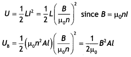
The magnetic energy per unit volume is
UB =
\(\frac{U_{B}}{V}=\frac{U_{B}}{A l}=\frac{B^{2}}{2 \mu_{0}}\)
Question 31.
Derive the expression for the self-inductance of a
solenoid.
Answer:
Consider a uniformly wound solenoid with N turns and
length l. Let the length of the solenoid be large as compared to its radius and
let the core of the solenoid have air. Due to this, we can take the interior
field uniform. Therefore the magnetic field in the interior of the solenoid is
given by
B = μ0 n l = μ0 \(\frac{N}{l}\) l …(1)
where n is the number of turns per unit length. The flux through each turn is
given by
Φm = B A = μ0 \(\frac{N A}{l}\) l …(2)
where A Is the area of cross-section of the solenoid. But
L = \(\frac{N
\Phi_{\mathrm{m}}}{I}\) …(3)
Therefore from equations (2) and (3) we have
L = \(\frac{N
\Phi_{m}}{l}=\frac{\mu_{0} N^{2} A}{l}\) ….(4)
This shows that L depends on the geometric factors and is proportional to the
square of the number of turns. Since N N = n l, we can therefore express the
above result as
L = µ0\(\frac{(n l)^{2}}{l}\)A = µ0
n2 A l …(5)
Question 32.
(a) State Faraday’s laws of electromagnetic Induction.
Answer:
Faraday’s Laws of electromagnetic induction
First law: Whenever
the magnetic flux (inked with a circuit (or coil) changes, an emf is induced in
the circuit. The induced emf Lasts so Long as the change in the magnetic flux
continues.
Second law:
The magnitude of induced emf in the circuit (or coil) is
directly proportional to the rate of change of magnetic flux linked with the
circuit.
i.e. e = – \(\frac{d \phi}{d t}\)
(b) Derive an expression for the emf induced across the ends of a straight
conductor of length I moving at right angles to a uniform magnetic field B with
a uniform speedy.
Answer:
Let a conductor ab of Length l be placed in a
magnetic field \(\vec{B}\) shown by (x) directed towards the reader. When the
conductor moves with velocity v perpendicular to B, the force on any free
electron of this conductor is given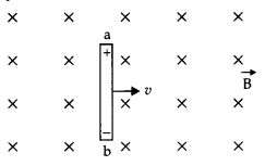
F = e vB sin 90° = evß
When this electron moves across the Length of the conductor, the work done by
the electron
W = F × l = evBl
After some time when all the free electrons are shifted towards the end b, the end b becomes negative and end a becomes positively charged.
Hence the net induced emf in the conductor
e = \(\frac{W}{q}=\frac{e v B
l}{e}=v B l\)
e = Blv
(c) Obtain the expression for the magnetic energy stored in a solenoid in
terms of the magnetic field B, area A and length I of the solenoid through which
a current j is passed. (CBSE 2019C)
Answer:
Energy stored in an inductor
Considers an inductor of inductance L. Let I will be instantaneous current in
the inductor and dl/dt be the rate of growth of current.
Induced emf, E = L\(\frac{dl}{dt}\) (in magnitude)
If the source sends a charge dq in time dt, then
dq = ldt
Small amount of work done by the source
dW = edq = eldt =
L\(\frac{dl}{dt}\). ldt
or
dW = Ll dl
Total work was done during the growth of current in an Inductor by the
external source
W = ∫dW =L∫01 ldl
= L
\(\left[\frac{l^{2}}{2}\right]_{0}=\frac{1}{2}\)Ll2
W =
\(\frac{1}{2}\) Ll2 …(1)
This work done is stored in the form of magnetic energy.
In a
solenoid,
L = μ0n2Al
And B = μ0nl
∴ l
= \(\frac{B}{\mu_{0} n}\)
So Eq. (1) becomes
W = \(\frac{1}{2}\)μ0n2Al\(\left(\frac{B}{\mu_{0}
n}\right)^{2}=\frac{B^{2} A l}{2 \mu_{0}}\)
Question 33.
(a) A metallic rod of length ‘l’ and resistance ‘R’ is
rotated with a frequency ‘v’ with one end hinged at the centre and the other end
at the circumference of a circular metallic ring of radius ‘l’, about an axis
passing through the centre and perpendicular to the plane of the ring. A
constant and uniform magnetic field ‘B’ parallel to the axis is present
everywhere.
(i) Derive the expression for the induced emf and the current in
the rod.
(ii) Due to the presence of current in the rod and of the magnetic
field, find the expression for the magnitude and direction of the force acting
on this rod.
(iii) Hence, obtain an expression for the power required to
rotate the rod.
(b) A copper coil l is taken out of a magnetic field with a
fixed velocity. Will it be easy to remove it from the same field if its ohmic
resistance is increased?
OR
(a) A rectangular coil rotates in a uniform
magnetic field. Obtain an expression for induced emf and current at any instant.
Also find their peak values. Show the variation of induced emf versus angle of
rotation (ωt) on a graph.
(b) An iron bar falling through the hollow region
of a thick cylindrical shell made of copper experiences a retarding force. What
can you conclude about the nature of the iron bar? Explain. (CBSEAI 2019)
Answer:
(a) (/) Let the rod moves from OP to OQ through a small sector of
angle θ.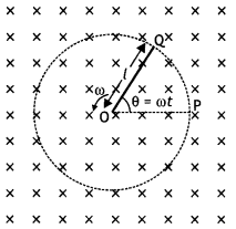
The
small area covered by the rod is
dA = πl2 × \(\frac{\theta}{2
\pi}=\frac{1}{2}\)l2θ
where L is the radius of the circle in which the rod rotates. Hence the
induced emf is
Now induced current is given by
i = \(\frac{\varepsilon}{R}=\frac{B \omega
l^{2}}{2 R}\)
(ii) \(\vec{F}=i(\vec{l} \times \vec{B})\)
F = \(\frac{l^{3} \omega B}{2
R}\)
Direction of \(\vec{F}\) is perpendicular to both \(\vec{i}\) and \(\vec{B}\),
(iii) P = i2R
= \(\left(\frac{B l^{2} \omega}{2
R}\right)^{2}\)R = \(\frac{B^{2} l^{4} \omega^{2}}{4 R}\)
(b) Yes, since induced current will reduce, it will be a little easier to
remove the coil.
Or
(a) Consider an armature of the ac generator having n
turns placed in a uniform magnetic field B.
Suppose at any instant t the normal to the plane of the coil makes an angle θ with the direction of the magnetic field. If ω is the uniform angular velocity with which the coil rotates then θ = ωt.
The flux through the loop is Φ = n BA cos Φ = n BA cos ω t
where n is the
number of turns in the armature.
By Faraday’s flux rule,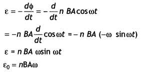
Now,i0 = \(\frac{\varepsilon_{0}}{R}=\frac{n B A \omega}{R}\)
The graph is as shown.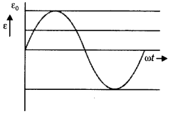
(b) The bar is magnetic in nature. It experiences retardation in accordance with
Lenz’s law.
Question 34.
State Lenz’s law. The energy f required to build up a steady
current l, in a given coil, varies with l in the manner as shown. Calculate the
self-inductance of the coil.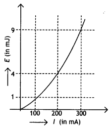
A circular coil of radius r, is placed coaxially with another coil of radius R
(R >> r) with the centre of the two coils coinciding with each other.
Obtain an expression for the mutual inductance of the two coils.
Answer:
Lenz’s law states that the direction of induced emf is such that it opposes the
cause of its production.
The energy stored in an inductor is given by the
relation
E = – \(\frac{1}{2}\)Ll2
From the graph for a current of 200 mA the energy is 4 mJ, therefore
self-inductance of the coil.
\(\frac{2 E}{l^{2}}\) = L
or
\(\frac{2
\times 4 \times 10^{-3}}{\left(200 \times 10^{-3}\right)^{2}}\) = 0.2 H
or
L = 200 mH
Consider the two coils of radius r and R placed coaxially, as shown in the
figure.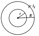
Let n1 and n2 be the number of turns per unit length in
them.
If a current l2 is passed through the outer coil, there will a
magnetic field
Bo = μo n1 l1
produced in it.
The flux associated with the inner coil will undergo variation as the field
B0 grows.
The effective magnetic flux
Φ1 = Bo ×
Aeff = \(\frac{\mu_{0} l_{2}}{2 R}\) × πr²
Therefore mutual inductance of the coils is
M =
\(\frac{\phi_{1}}{l_{2}}=\frac{\mu_{0} \pi r^{2}}{2 R}\)
Question 35.
(a) Describe a simple experiment (or activity) to show that
the polarity of emf induced in a coil is always such that it tends to produce a
current which opposes the change of magnetic flux that produces it.
(b) The
current flowing through an inductor of self-inductance L is continuously
increasing. Plot a graph showing the variation of
(i) Magnetic flux versus
the current
(ii) induced emf versus dl/dt
(iii) Magnetic potential energy
stored versus the current. (CBSE Delhi 2014)
Answer:
(a) Consider a coil C
connected to a galvanometer. When the North Pole of a bar magnet is pushed
towards the coil, the pointer in the galvanometer deflects, indicating the
presence of electric current in the coil. When the magnet is pulled away from
the coil, the galvanometer shows deflection in the opposite direction, which
indicates a reversal of the current’s direction.
We see that the North Pole of a bar magnet is being pushed towards the closed coil. As the North Pole of the bar magnet moves towards the coil, the magnetic flux through the coil increases. Hence current is induced in the coil in such a direction that it opposes the increase in flux.
This is possible only if the current in the coil is in a counter-clockwise direction with respect to an observer situated on the side of the magnet. Similarly, if the North Pole of the magnet is being withdrawn from the coil, the magnetic flux through the coil will decrease. To counter this decrease in magnetic flux, the induced current in the coil flows in a clockwise direction and the South Pole faces the receding North Pole of the bar magnet. This would result in an attractive force that opposes the motion of the magnet and the corresponding decrease in flux.
(b) The graphs are as shown.
(i) Φ = Ll
Therefore the graph is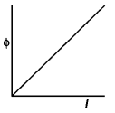
(ii) ε = – L\(\frac{dl}{dt}\)
Therefore the graph is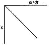
(iii) U = \(\frac{1}{2}\)Ll2
Therefore the graph is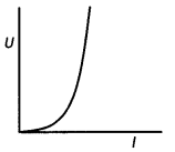
Numerical Problems:
Formulae for solving numerical problems
- Induced emf ε = –\(\frac{d \phi}{d t}\)
or
ε = \(\frac{-\left(\phi_{2}-\phi_{1}\right)}{t_{2}-t_{1}}\) - Emf induced in a rod of Length L is ε = Blv.
- When a conducting rod of length L kept perpendicular to a uniform magnetic
field B is rotated about one of its ends with uniform angular velocity, the
emf induced between its ends has a magnitude
\(\frac{1}{2}\)BωL2 = BπvL2. - When a current in a coil changes, it induces a back emf in the same coil.
The self-induced emf is given by
ε = – \(\frac{d \phi}{d t}\) = – L \(\frac{d l}{d t}\) inductance of the coil. It is a measure of the inertia of the coil against the change of current through it. Also Φ = L l - ε = – M\(\frac{d l}{d t}\) . Also Φ = Ml for mutual induction.
- \(\frac{V_{s}}{V_{p}}=\frac{N_{s}}{N_{p}}=\frac{l_{p}}{l_{s}}\) = k.
- Average power η = \(\frac{\varepsilon_{s} l_{s}}{\varepsilon_{p} l_{p}}\)
Question 1.
A square loop of side 10 cm with its sides parallel to X and Y
axes is moved with a velocity of 8 cm s-1 in the positive X-direction
containing a magnetic field in the positive Z-direction. The field is
non-uniform and has a gradient of 10-3 T cm-1 along the
negative X-direction (i.e. it increases by 10-3 T cm-1 as
one move in the negative X-direction). Calculate the emf induced. (CBSE
2019C)
Answer: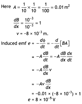
Question 2.
In a ceiling fan, each blade rotates in a circle of radius 0.5 m.
If the fan makes 2 rotations per second and the vertical component of the
earth’s magnetic field is 8 × 10⁻⁵ T, calculate the emf induced
between the inner and outer ends of each blade. (CBSE2019C)
Answer: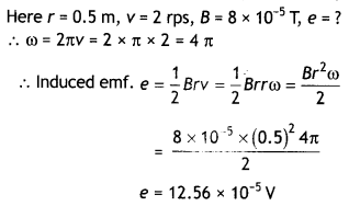
Question 3.
A circular coil of radius 10 cm, 500 turns and resistance 2 Ω are
placed with its plane perpendicular to the horizontal component of the earth’s
magnetic field. It is rotated about its vertical diameter through 180° in 0.25
s. Estimate the magnitudes of the emf and the current induced in the coil. The
horizontal component of the earth’s magnetic field at the place is 3.0 ×
10-5 T. (NCERT)
Answer:
Initial flux through the
coil
Φin = BA cos θ = 3.0 × 10⁻⁵ × π × 10-2
× cos 0°
= 3π × 10-7 Wb
Final flux after the rotation
Φf = BA cos θ = 3.0 ×
10-5 × π × 10-2 × cos 180° = – 3π × 10-7 Wb
Therefore estimated value of induced emf is
ε = n\(\frac{d \phi}{d t}\) =
500 × (6π × 10-7)/ 0.25 = 3.8 × 10⁻³ V dt
Hence the current induced is
l = ε/R = 3.8 × 10⁻³ / 2 = 1.9 ×
10-3 A
Question 4.
Kamla peddles a stationary bicycle. The pedals of the bicycle
are attached to a 100 turn coil of area 0.10 m2. The coil rotates at
half a revolution per second and is placed in a uniform magnetic field of 0.01 T
perpendicular to the axis of rotation of the coil. What is the maximum voltage
generated in the coil? (NCERT)
Answer:
Given n = 100, A = 0.10 m2, B =
0.01 T, f = 0.5 rps
Using the expression ε0 = nBAω
we have ε0 = 100 × 0.01 × 0.10 × 2 × 3.14 × 0.5 = 0.314 V
Question 5.
A rectangular wire loop of sides 8 cm and 2 cm with a small
cut is moving out of a region of the uniform magnetic field of magnitude 0.3 T
directed normal to the loop. What is the emf developed across the cut if the
velocity of the loop is 1 cm s-1 in a direction normal to the (a)
longer side, (b) shorter side of the loop? For how long does the induced voltage
last in each case? (NCERT)
Answer:
Given L = 8 cm = 8 × 10⁻² m,
b = 2 cm = 2 × 10⁻² m, 8 = 0.3 T, v = 1 cm s-1 = 0.01 m
s-1 ε = ?
(a) Using the expression ε = B L v
ε = 0.3 × 8 ×
10-2 × 0.01 = 2.4 × 10⁻⁴ V
This emf will last till the loop comes out of the magnetic field. Since the shorter side is moving out, therefore it will take 2 s to cover 2 cm with a velocity of 1 cm s-1.
(b) Using the expression e = B L v
ε = 0.3 × 2 × 10-2 × 0.01 =
0.6 × 10⁻⁴ V
This emf will last till the loop comes out of the magnetic field. Since the longer side is moving out, therefore it will take 8 s to cover 8 cm with a velocity of 1 cm s-1.
Question 6.
A 1.0 m long metallic rod is rotated with an angular frequency
400 rad s-1 about an axis normal to the rod passing through its one end. The
other end of the rod is in contact with a circular metallic ring. A constant and
uniform magnetic field of 0.5 T parallel to the axis exists everywhere.
Calculate the emf developed between the centre and the ring. (NCERT)
Answer:
Given L = 1.0 m, ω = 400 rad s-1, B = 0.5 T,
ε = ? Using the relation ε = \(\frac{1}{2}\)BωL2
we have
ε = \(\frac{1}{2}\)0.5 × 400 × 12 =100 V
Question 7.
A circular coil of radius 8.0 cm and 20 turns is rotated about
its vertical diameter with an angular speed of 50 rad s-1 in a
uniform horizontal magnetic field of magnitude 3.0 × 10⁻² T. Obtain
the maximum and average emf induced in the coil. If the coil forms a closed loop
of resistance 10 Ω, calculate the maximum value of current in the coil.
Calculate the average power loss due to Joule heating. Where does this power
come from? (NCERT)
Answer:
Given r = 8.0 cm = 8.0 × 10⁻² m, n =
20, ω = 50 rad s-1 B = 3.0 × 10⁻² T, ε0 = ?, εa
= ? R= 10 Ω l = ?, P = ?
Using the relation
ε0 = nBAω
= 20 × 3 ×
10-2 × 3.14 × (8 × 10-2)2 × 50 = 0.603 V
The average induced emf is given by
εa = 0 over one cycle.
Also l0 = ε0 / R
= 0.603 / l0
= 0.0603
A
Now P = 1 /2 ε0 × l0 = 1 /2 × 0.603 × 0.0603
= 0.018
W
The induced current causes a torque opposing the rotation of the coil. An external agent (rotor) must supply torque to counter this torque in order to keep the coil rotating uniformly. Thus the source of the power dissipated as heat in the coil is the external rotor.
Question 8.
Current in a circuit falls from 5.0 A to 0. 0 A in 0.1 s. If
an average emf of 200 V induced, give an estimate of the self-inductance of the
circuit (NCERT)
Answer:
Given dl = 5.0 – 0.0 = 5.0 A, dt = 0.1 s, ε = 200
V, L = ?
Using the relation ε = – L \(\frac{dl}{dt}\)
or
L =
\(\frac{\varepsilon}{d l / d t}\)
L = \(\frac{200}{5 / 0.1}=\frac{200 \times 0.1}{5}\) = 4 H
Question 9.
A pair of adjacent coils has a mutual inductance of 1.5 H. If
the current in one coil changes from 0 to 20 A in 0.5 s, what is the change of
flux linkage with the other coil? (NCERT)
Answer:
Given dl = 20- 0.0 = 20
A, dt = 0.5 s, ε = ?,
M = 1.5 H,
Using the relation ε = – \(\frac{d
\phi}{d t}\) = -M\(\frac{dl}{dt}\)
or
dΦ = Mdl = 1.5 × 20 = 30 Wb
Question 10.
A jet plane is travelling towards the west at a speed of 1800
km h-1. What is the voltage difference developed between the ends of
the wing having a span of 25 m, if the earth’s magnetic field at the location
has a magnitude of 5 × 10⁻⁴ T and the dip angle is 30°? (NCERT)
Answer:
Given v= 1800 km h-1, ε = ?, L = 25 m,
B = 5 × 10⁻⁴ T,
δ = 30°
Now vertical component of earth’s magnetic field is
BV
= B × sin 30°
= 5 × 10-4 × 0.5
= 2.5 × 10⁻⁴T
Now
using the expression ε = B L v
ε = 2.5 × 10-4 × 25 × 500 = 3.125
V
Question 11.
1 MW power is to be delivered from a power station to a town
10 km away. One uses a pair of Cu wires of a radius of 0.5 cm for this purpose.
Calculate the fraction of ohmic losses to the power transmitted if
(a) power
is transmitted at 220 V. Comment on the feasibility of doing this.
(b) a
step-up transformer is used to boost the voltage to 11000 V, power transmitted,
then a step-down transformer is used to bring the voltage to 220 V.
ρcu = 1.7 × 10⁻⁸ SI unit. (NCERT Exemplar)
Answer:
Given P = 1 MW, 2L = 20 km = 2 × 10⁴ m, r = 0.5 cm = 0.5 × 10⁻² m
(a) Resistance of the Cu wire used
R = \(\frac{\rho L}{A}=\frac{1.7 \times
10^{-8} \times 2 \times 10^{4}}{\pi \times\left(0.5 \times 10^{-2}\right)^{2}}\)
= 4 Ω
Now current at 220 V is
l = \(\frac{P}{V}=\frac{10^{6}}{220}\) = 0.45 × 10⁴ A
Therefore power loss
= l2R = (0.45 ×
104)2 × 4 = 106W
This is a huge loss; therefore this method is not feasible.
(b) Now P = Vl’ or
l’ =
\(\frac{P}{V^{\prime}}=\frac{10^{6}}{11000}=\frac{1}{1.1}\) × 102
A
Hence power loss
= l’2R = \(\frac{1}{1.21}\) × 4 ×
104 = 3.3 × 10⁴ W
Hence fraction of power loss
\(\frac{3.3 \times 10^{4}}{10^{6}}\) =
3.3%