Moving Charges And Magnetism
Class 12th Physics Chapter Important Questions
Class 12 Physics Chapter 4 Important Questions Moving Charges and Magnetism
Very Short Answer
Question 1.
What is the direction of the force acting on a charged
particle q, moving with a velocity \(\overrightarrow{\mathbf{v}}\) in a uniform
magnetic field B? (Delhi)
Answer:
The direction of the force acting on a
charged particle q, moving with a velocity \(\overrightarrow{\mathbf{v}}\) in a
uniform
magnetic field \(\overrightarrow{\mathbf{B}}\) is perpendicular to
the plane of vectors \(\overrightarrow{\mathbf{v}}\) and
\(\overrightarrow{\mathbf{B}}\)![]()
So, force is perpendicular to both
\(\overrightarrow{\mathbf{v}}\) and \(\overrightarrow{\mathbf{B}}\). From
equation (i), we can also say that the force \(\overrightarrow{\mathbf{F}}\)
acts in the direction of the vectors \(\overrightarrow{\mathbf{v}}\) and
\(\overrightarrow{\mathbf{B}}\)
Question 2.
Why should the spring/suspension wire in a moving coil
galvanometer have low torsional constant? (All India 2008)
Answer:
Low
torsional constant is basically required to increase the current/charge
sensitivity in a moving coil ballistic galvanometer.
Question 3.
Magnetic field lines can be entirely confined within the core
of a toroid, but not within a straight solenoid. Why? (Delhi 2008)
Answer:
At the edges of the solenoid, the field lines get diverged due to
other fields and/or non-availability of dipole loops, while in toroids the
dipoles (in loops) orient continuously.
Question 4.
An electron does not suffer any deflection while passing
through a region of uniform magnetic field. What is the direction of the
magnetic field? (All India 2009)
Answer:![]()
∴Magnetic field will be in the line of the velocity of
electron.
Question 5.
A beam of a particles projected along +x-axis, experiences a
force due to a magnetic field along the +y-axis. What is the direction of the
magnetic field? (All India 2009)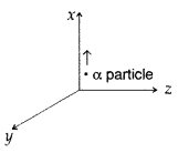
Answer:![]()
Direction of the magnetic field is towards negative direction
of z-axis.
Question 6.
A beam of electrons projected along +x-axis, experiences a
force due to a magnetic field along the +y/-axis. What is the direction of the
magnetic field? (All India 2010)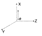
Answer:
Direction of the magnetic field is F = q (v × B)
towards positive direction of z-axis.
Question 7.
A beam of protons, projected along + x-axis, experiences a
force due to a magnetic field along the – y-axis. What is the direction of the
magnetic field? (All India 2010)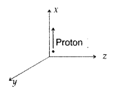
Answer:
The direction of the magnetic field is towards
positive direction of z-axis.
Question 8.
Depict the trajectory of a charged particle moving with
velocity v as it enters a uniform magnetic field perpendicular to the direction
of its motion. (Comptt. All India 2012)
Answer: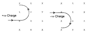
The force acting on the charge particle will be perpendicular
to both v and S and therefore will describe a circular path.
Question 9.
Write the expression in vector form, for the magnetic force
\(\overrightarrow{\mathrm{F}}\) acting on a charged particle moving with
velocity \(\overrightarrow{\mathrm{V}}\) in the presence of a magnetic field B.
(Comptt. All India 2012)
Answer:
Question 10.
An ammeter of resistance 0.6 Ω can measure current upto 1.0
A. Calculate
(i) The shunt resistance required to enable the ammeter to
measure current upto 5.0 A
(ii) The combined resistance of the ammeter and
the shunt. (Delhi 2013)
Answer:

Question 11.
Write the expression, in a vector form, for the Lorentz
magnetic force \(\overrightarrow{\mathrm{F}}\) due to a charge moving with
velocity \(\overrightarrow{\mathrm{V}}\) in a magnetic field
\(\overrightarrow{\mathrm{B}}\). What is the direction of the magnetic force?
(Delhi 2013)
Answer:![]()
… [q is the magnitude of the moving charges)
This force is
normal to both the directions of velocity \(\overrightarrow{\mathrm{V}}\) and
magnetic field \(\overrightarrow{\mathrm{B}}\) .
Question 12.
Using the concept of force between two infinitely long
parallel current carrying conductors, define one ampere of current. (All India
2013)
Answer:![]()
“One ampere of current is the value of steady current, which
when maintained in each of the two very long, straight, parallel conductors of
negligible cross-section; and placed one metre apart in vacuum, would produce on
each of these conductors a force of equal to 2 × 10⁻⁷ newtons per
metre (Nm-1) of length. ”
Question 13.
Write the condition under which an electron will move
undeflected in the presence of crossed electric and magnetic fields.(Comptt. All
India 2013)
Answer:![]()
and electric and magnetic fields are mutually
perpendicular.
Question 14.
Why do the electrostatic field lines not form closed loops?
(All India 2015)
Answer:
Electric field lines do not form closed loops
because the direction of an electric field is from positive to negative charge.
So one can regard a line of force starting from a positive charge and ending on
a negative charge. This indicates that electric field lines do not form closed
loops.
Question 15.
A particle of mass ‘m’ and charge ‘q’ moving with velocity V
enters the region of uniform magnetic field at right angle to the direction of
its motion. How does its kinetic energy get affected? (Comptt. Delhi 2015)
Answer:
Kinetic energy will NOT be affected.
*(When \(\vec{v}\) is
perpendicular to \(\vec{B}\), then magnetic field provides necessary centripetal
force)
Question 16.
Write the underlying principle of a moving coil galvanometer.
(Delhi 2015)
Answer:
Principle of a galvanometer : “A current carrying
coil, in the presence of magnetic field, experiences a torque which produces
proportionate deflection”.![]()
Question 17.
A coil, of area A, carrying a steady current I, has a
magnetic moment, \(\vec{m}\), associated with it. Write the relation between
\(\vec{m}\), I and A in vector form. (Comptt Delhi 2015)
Answer:
Relation
for magnetic moment = \(\vec{m}\) = I\(\vec{A}\)
Question 18.
Under what condition is the force acting on a charge moving
through a uniform magnetic field minimum?
Answer:
When the charge moves
parallel to the direction of the magnetic field.
Question 19.
What Is the nature of the magnetic field in a moving coil
galvanometer?
Answer:
Radial magnetic field.
Question 20.
State two properties of the material of the wire used for
suspension of the coil in a moving coil galvanometer.
Answer:
- High tensile strength.
- SmalL vaLue of torque per unit twist.
Question 21.
Write one condition under which an electric charge does not
experience a force in a magnetic field.
Answer:
When it moves parallel to
the direction of the magnetic field.
Question 22.
Mention the two characteristic properties of the material
suitable for making the core of a transformer. (CBSE AI 2012)
Answer:
- Low retentivity
- High permeability
Question 23.
Write the expression, in a vector form, for the Lorentz
magnetic force due to a charge moving with velocity \(\vec{V}\) in a magnetic
field \(\vec{B}\). What is the direction of the magnetic force? (CBSE Delhi
2014)
Answer:
The expresion is \(\vec{F}\) = q(\(\vec{V}\) × \(\vec{B}\)).
The force is perpendicular to both the velcoity and the magentic field
vector.
Question 24.
Write the condition under which an electron will move
undeflected in the presence of crossed electric and magnetic fields. (CBSE Al
2014C)
Answer:
An electron moves perpendicular to both fields.
Question 25.
What can be the cause of the helical motion of a charged
particle?
Answer:
The charge enters the magnetic field at
any angle except 0°, 180°, and 90°.
Question 26.
Write the underlying principle of a moving coil galvanometer.
Answer:
A current-carrying loop placed in a magnetic
field experiences a torque.
Question 27.
A proton and an electron traveling along parallel paths enter
a region of the uniform magnetic field, acting perpendicular to their paths.
Which of them will move in a circular path with a higher frequency? (CBSEAI and
Delhi 2018)
Answer:
The frequency of revolution is given by
v =
\(\frac{B q}{2 \pi m}\) ⇒ v ∝ \(\frac{1}{m}\) .
As for me < mp
therefore ve
>vp
Question 28.
Two protons of equal kinetic energies enter a region of the
uniform magnetic field. The first proton enters normal to the field direction
while the second enters at 30° to the field direction. Name the trajectories
followed by them. (CBSEAI and Delhi 2018C)
Answer:
Normal: circular
At
an angle of 30°, it will follow a helical path.
Question 29.
Consider the circuit shown here where APB and AQB are
semi-circles. What will be the magnetic field at the center C of the circular
loop?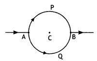
Answer:
Zero, because magnetic fields due to APB and AQB are equal in
magnitudes but opposite in directions.
Question 30.
Which one of the following will have a minimum frequency of
revolution,
when projected with the same velocity v perpendicular to the
magnetic field B: (i) α – particle and (ii) β – particle.
Answer:
Frequency of revolution v = \(\frac{q B}{2 \pi m}\) and \(\frac{q}{m}\) of α –
particle is less, hence α – particle will have minimum frequency of
revolution.
Question 31.
An ammeter and a milli-ammeter are converted from the same
galvanometer. Out of the two, which current-measuring instrument has higher
resistance?
Answer:
A milli-ammeter has higher resistance.
Question 32.
Equal currents I and I are flowing through two infinitely
long parallel wires. What will be the magnetic field at a point mid-way when the
currents are flowing in the same direction?
Answer:
Zero, because fields
due to two wires will be equal but opposite.
Question 33.
The figure shows a circular loop carrying current l. Show the
direction of the magnetic field with the help of lines of![]()
Answer:
The magnetic field lines are as shown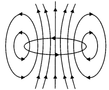
Question 34.
An electron is moving with velocity v along the axis of a long
straight solenoid carrying current I. What will be the force acting on the
electron due to the magnetic field of the solenoid?
Answer:
Zero, as a
force on a charged particle moving in a magnetic field, is F= Bqv sin θ
Here
both v and B are along the axis of – solenoid, so θ = 0° between them. Hence F=
qvB sin θ = 0.
Short Answer Type
Question 1.
Using Ampere’s circuital law, obtain an expression for the
magnetic field along the axis of a current carrying solenoid of length l and
having N number of turns.
Answer:
Magnetic field due to
Solenoid Let length of solenoid = L
Total number of turns in solenoid = N
No. of turns per unit length = \(\frac{N}{L}\) = n
ABCD is an Ampere’s
loop
AB, DC are very large
BC is in a region of
\(\overrightarrow{\mathrm{B}}\) = 0
AD is a long axis
Length of AD = x
Current in one turn = I0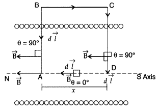
Applying Ampere’s circuital loop — | B .dl = go I ’
![]()
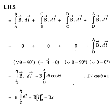
No. of turns in x length = nx,
Current in turns nx, I = nx
I0
According to Ampere’s circuital law
Bx = µ0 I
=> Bx = µ0 nx I0
∴ B =
µ0nI0
Question 2.
A charge ‘q’ moving B along the X-axis with a velocity v is
subjected to a uniform magnetic field B acting along the Z-axis as it crosses
the origin O. (Delhi 2009)
(i) Trace its trajectory.
(ii) Does the charge
gain kinetic energy as it enters the magnetic field? Justify your
answer.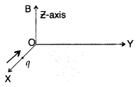
Answer: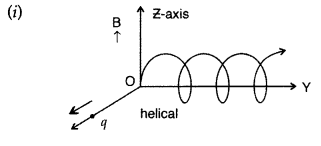
(ii) K.E does not change irrespective of the direction of the
charge as
Question 3.
State Biot-Savart law.
A current I flows in a conductor
placed perpendicular to the plane of the paper. Indicate the direction of the
magnetic field due to a small element \(\overrightarrow{d \vec{l}}\) at point P
situated at a distance \(\vec{r}\) from the element as shown in the
figure.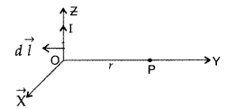
Answer:
Biot-Savart law and its applications :
Biot-Savart law states that “the magnitude of the magnetic field dB at any point
due to a small current element dl is given by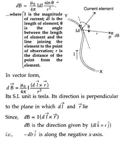
Question 4.
(a) In what respect is a toroid different from a solenoid?
Draw and compare the pattern of the magnetic field lines in the two cases.
(b) How is the magnetic field inside a given’ solenoid made strong? (All India
2011)
Answer:
(a) Solenoid consists of a long wire wound in the form of a
helix where the neighbouring turns are closely spaced, whereas, the toroid is a
hollow circular ring on which a large number of turns of a wire is closely
wound.
(b) Magnetic field inside a given solenoid is made strong by putting a
soft iron core inside it. It is strengthened by increasing the amount of current
through it.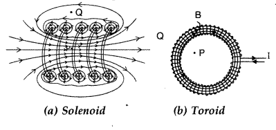
Question 5.
Write the expression for Lorentz magnetic force on a particle
of charge ‘q’ moving with velocity \(\vec{v}\) in a magnetic field \(\vec{B}\).
Show that no work is done by this force on the charged particle. (All India
2011)
Answer:
Expression for Lorentz magnetic force on a particle of
charge ‘q’ moving with velocity \(\vec{v}\) in a magnetic field \(\vec{B}\) is
\(\vec{F}\) = q(\(\vec{E}\) + \(\vec{v}\) × \(\vec{B}\))
Work done by a
magnetic force on a charged particle :
The magnetic force
\(\overrightarrow{\mathrm{F}}=q(\overrightarrow{\mathrm{E}}+\vec{v} \times
\overrightarrow{\mathrm{B}})\) always acts perpendicular to the velocity
\(\vec{v}\) on the direction of motion of charge q.![]()
Question 6.
A steady current (I1) flows through a long
straight wire. Another wire carrying steady current (I2) in the same
direction is kept close and parallel to the first wire. Show with the help of a
diagram how the magnetic field due to the current I1 exerts a
magnetic force on the second wire. Write the expression for this force. (All
India 2011)
Answer:
Consider two infinitely long parallel conductors
carrying current I1 and I2 in the same direction.
Let d
be the distance of separation between these two conductors.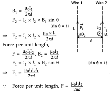
Hence, force is attractive in nature.
Ampere : Ampere is
that current which is if maintained in two infinitely long parallel conductors
of negligible cross-sectional area separated by 1 metre in vacuum causes a force
of 2 × 10⁻⁷ N on each metre of the other wire.
Then current
flowing is 1A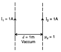

Question 7.
Using Ampere’s circuital law, obtain the expression for the
magnetic field due to a long solenoid at a point inside the solenoid on its
axis.
Answer:
Magnetic field due to Solenoid Let length
of solenoid = L
Total number of turns in solenoid = N
No. of turns per
unit length = \(\frac{N}{L}\) = n
ABCD is an Ampere’s loop
AB, DC are very
large
BC is in a region of \(\overrightarrow{\mathrm{B}}\) = 0
AD is a
long axis
Length of AD = x
Current in one turn = I0 Applying Ampere’s circuital loop — | B .dl = go I ’
![]()

No. of turns in x length = nx,
Current in turns nx, I = nx
I0
According to Ampere’s circuital law
Bx = µ0 I
=> Bx = µ0 nx I0
∴ B =
µ0nI0
Question 8.
Two identical circular wires P and Q each of radius R and
carrying current ‘I’ are kept in perpendicular planes such that they have a
common centre as shown in the figure. Find the magnitude and direction of the
net magnetic field at the common centre of the two coils. (Delhi 2011)
Answer:
Magnetic field produced by the two coils at their
common centre are: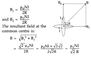

The net magnetic field is directed at an angle of 45° with
either of the fields.
Question 9.
Two identical circular loops, P and Q, each of radius r and
carrying current I and 21 respectively are lying in parallel planes such that
they have a common axis. The direction of current in both the loops is clockwise
as seen from O which is equidistant from both the loops. Find the magnitude of
the net magnetic field at point O. (Delhi 2011)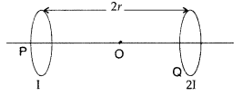
Answer:
When the currents are in the same direction, the
resultant field at point O is,
Question 10.
Two identical circular loops, P and Q, each of radius r and
carrying equal currents are kept in the parallel planes having a common axis
passing through O. The direction of current in P is clockwise and in Q is
anti-clockwise as seen from O which is equidistant from the loops P and Q. Find
the magnitude of the net magnetic field at O. 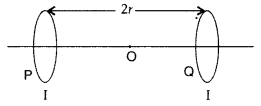
Answer: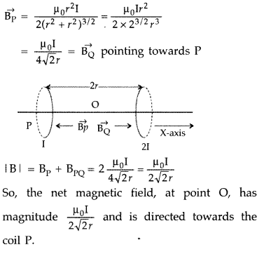
Question 11.
A circular coil of closely wound N turns and radius r carries
a current I. Write the expressions for the following :
(i) the magnetic field
at its centre
(ii) the magnetic moment of this coil
Answer:
(i) The magnetic field at the centre of a circular coil of N turns
and radius r carrying a current, I is![]()
(iii) Magnetic moment, M = NIA = NIπr2
Question 12.
A proton and a deuteron, each moving with velocity
\(\vec{v}\) enter simultaneously in the region of magnetic field \(\vec{B}\)
acting normal to the direction of velocity. Trace their trajectories
establishing the relationship between the two. (Comptt. Delhi 2011)
Answer: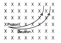
Question 13.
A particle of mass 10-3 kg and charge 5 pC enters
into a uniform electric field of 2 × 10⁵ NC-1, moving with
a velocity of 20 ms-1 in a direction opposite to that of the field.
Calculate the distance it would travel before coming to rest. (Comptt. Delhi
2011)
Answer: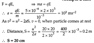
Question 14.
A particle of mass 2 x 10⁻³ kg and charge 2 µC
enters into a uniform electric field of 5 × 10⁵ NC-1,
moving with a velocity of 10 ms-1 in a direction opposite to that of
the field. Calculate the distance it would travel before coming to rest.
(Comptt. Delhi 2011)
Answer:
Force applied on the charged particle, f =
qE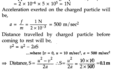
Question 15.
A particle of mass 5 × 10⁻³ kg and charge 4 µC
enters into a uniform electric field of 2 × 10⁵ NC-1,
moving with a velocity of 30 ms-1 in a direction opposite to that of
the field. Calculate the distance it would travel before coming to rest.
Answer:
Force applied on the charged
particle,![]()
Acceleration exerted on the charged particle when it enters
in electric field.
Distance travelled by charged particle before coming to rest
will be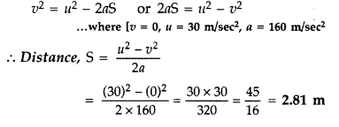
Question 16.
An ammeter of resistance 0.80 Ω can measure current upto 1.0
A.
(i) What must be the value of shunt resistance to enable the ammeter to
measure current upto 5.0A?
(ii) What is the combined resistance of the
ammeter and the shunt? (Delhi 2013)
Answer: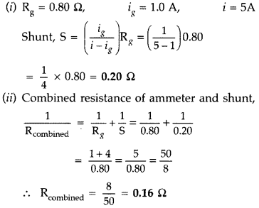
Question 17.
(a) How is a toroid different from a solenoid?
(b) Use
Ampere’s circuital law to obtain the magnetic field inside a toroid.
(c) Show
that in an ideal toroid, the magnetic field
(i) inside the toroid and
(ii)
outside the toroid at any point in the open space is zero. (Comptt. All India
2014)
Answer:
(a) A toroid is essentially a solenoid which has been bent
into a circular shape to close on itself.
(b)
(b) A toroid is a solenoid bent to form a ring shape.
Let N number of
turns per unit length of toroid and I be current flowing in it.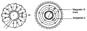
Consider a loop (region II) of radius r passes through the
centre of the toroid.
Let (region II) \(\overrightarrow{\mathrm{B}}\) be
magnetic field along the loop is
Let (region I) B1 be magnetic field outside toroid
in open space. Draw an amperian loop L2 of radius r2
through point Q.
Now applying ampere’s law :
As I = 0, because the circular turn current coming out of
plane of paper is cancelled exactly by current going into it, so net I = 0,
equation (i) becomes
(c) For the loop 1, Ampere’s circuital law gives,![]()
Thus the magnetic field, in the open space inside the toroid
is zero.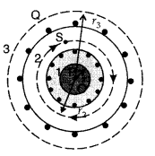
Also at point Q, we have![]()
But from the sectional cut, we refer to that the current
coming out of the plane of the paper is cancelled exactly by the current going
into it
Hence Ienclosed = 0
∴ B3 = 0
Question 18.
Derive an expression for the magnetic moment (\(\vec{\mu}\))
of an electron revolving around the nucleus in terms of its angular
momentum ![]() . What is the direction of* the magnetic moment of the electron
with respect to its angular momentum? (Comptt. All India 2014)
. What is the direction of* the magnetic moment of the electron
with respect to its angular momentum? (Comptt. All India 2014)
Answer: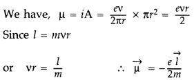
[ ∴ electron has a negative charge
The direction of
(\(\vec{\mu}\)) is opposite to that of ![]() , because of the negative charge of the electron.
, because of the negative charge of the electron.
Question 19.
State the underlying principle of a cyclotron. Write briefly
how this machine is used to accelerate charged particles to high energies.
(Delhi 2014)
Answer:
Principle : When a positively charged particle is
made to move again and again in a high frequency electric field, it gets
accelerated and acquires sufficiently large amount of energy.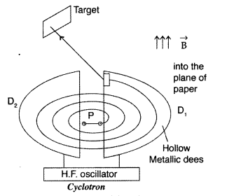
Working : Suppose a positive ion, say a proton, enters the
gap between the two dees and finds dee D1 to be negative. It gets
accelerated towards dee D1. As it enters the dee D1, it
does not experience any electric field due to shielding
effect of the
metallic dee. The perpendicular magnetic field throws it into a circular
path.
At the instant the proton comes out of dee D1. It finds dee
D1 positive and dee D2 negative. It now gets accelerated
towards dee D2. It moves faster through dee D2 describing
a larger semicircle than
before. Thus if the frequency of the applied voltage
is kept exactly the same as the frequency of the revolution of the proton, then
everytime the proton reaches the gap between the two dees, the electric field is
reversed and proton receives a push and finally it acquires very high energy.
This proton follows a spiral path. The accelerated proton is ejected through a
window by a deflecting voltage and hits the target.
Centripetal force is
provided by magnetic field to charged particle to move in a circular
back.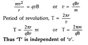
Question 20.
Draw the magnetic field lines due to a current passing
through a long solenoid. Use Ampere’s circuital law, to obtain the expression
for the magnetic field due to the current I in a long solenoid having n number
of turns per unit length. (Comptt. Delhi 2014)
Answer: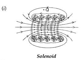
(ii) Expression for magnetic field :
Magnetic field due to
Solenoid Let length of solenoid = L
Total number of turns in solenoid = N
No. of turns per unit length = \(\frac{N}{L}\) = n
ABCD is an Ampere’s
loop
AB, DC are very large
BC is in a region of
\(\overrightarrow{\mathrm{B}}\) = 0
AD is a long axis
Length of AD = x
Current in one turn = I0
Applying Ampere’s circuital loop — | B .dl = go I ’![]()

No. of turns in x length = nx,
Current in turns nx, I = nx
I0
According to Ampere’s circuital law
Bx = µ0 I
=> Bx = µ0 nx I0
∴ B =
µ0nI0
Question 21.
A rectangular coil of sides ‘V and ‘b’ carrying a current I
is subjected to a uniform magnetic field \(\overrightarrow{\mathbf{B}}\) acting
perpendicular to its plane. Obtain the expression for the torque acting on
it.
Answer:
(a) Torque on a rectangular current
loop in a uniform magnetic field:
Let I = current through the coil
a, b –
sides of the rectangular loop
A = ab = area of the loop
n = Number of
turns in the loop
B = Magnetic field
θ = angle between magnetic field
\(\overrightarrow{\mathrm{B}}\) and area vector
\(\overrightarrow{\mathrm{A}}\)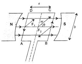
Force exerted on the arm DA inward
F1 = I b B
…[∵ F = ILB]
Force exerted on the arm BC outward
F2 = I b B ∴
F2 = F1
Thus net force on the loop is zero
∴ Two
equal and opposite forces form a couple which exerts a torque
∴ Magnitude of
the torque on the loop is,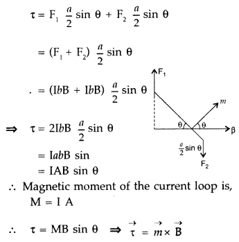
If loop has n turns then M = n I A
∴ τ = nIAB sin
θ
When θ = 90° then \(\tau_{\max }=n I A B\)
When θ = 0° then τ = 0
(b)
Since the momentum and the charge on both the proton and deutron are the same,
the particle will follow a circular path with radius 1:1.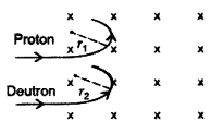
Question 22.
(i) State Biot – Savart law in vector form expressing the
magnetic field due to an \(\overrightarrow{\mathbf{B}}\) element
\(\overrightarrow{\mathbf{dl}}\) carrying current I at a distance
\(\overrightarrow{\mathbf{r}}\) from the element.
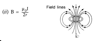
(ii) Write the expression
for the magnitude of the magnetic field at the centre of a circular loop of
radius r carrying a steady current I. Draw the field lines due to the current
loop. (Comptt. All India 2014)
Answer:
(i) According to Biot-Savart’s law,
“magnetic field acting at a particular point due to current carrying element is
proportional to the division of cross product of current element and position
vector of point where the field is to be calculated from the current element to
the cube of the distance between current element and the point where the field
is to be calculated”.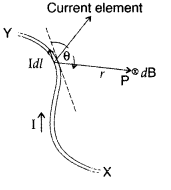

Magnetic field on the axis of circular current loop :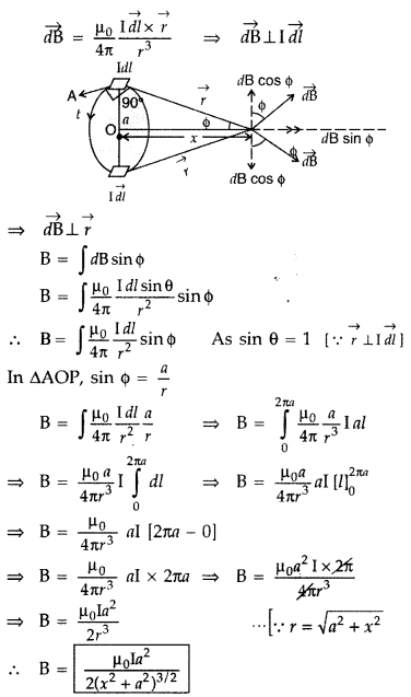
As in a special case we may obtain the field at the centre of
the loop. Here x = 0, and we obtain![]()
In a current loop, both the opposite faces behave as opposite
poles, making it a magnetic dipole. One side of the current carrying coil
behaves like the N-pole and the other side as the S-pole of a magnet.
Question 23.
A square loop of side 20 cm carrying current of 1A is kept
near an infinite long straight wire carrying a current of 2A in the same plane
as shown in the figure.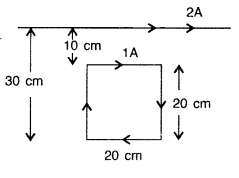
Calculate the magnitude and direction of the net force
exerted on the loop due to the current carrying conductor. (Comptt. All
India)
Answer:
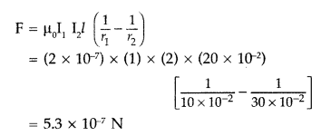
The direction of force is towards the infinitely long
straight wire.
Question 24.
A square shaped plane coil of area 100 cm2 of 200 turns
carries a steady current of 5A. It is placed in a uniform magnetic field of 0.2
T acting perpendicular to the plane of the coil. Calculate the torque on the
coil when its plane makes an angle of 60° with the direction of the field. In
which orientation will the coil be in stable equilibrium? (Comptt. All India
2014)
Answer: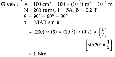
The coil will be in stable equilibrium when it is parallel to
the magnetic field.
Question 25.
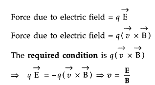
Find the condition under which the charged particles moving
with different speeds in the presence of electric and magnetic field vectors can
be used to select charged particles of a particular speed. (All India 2015)
Answer:
Condition: The velocity \(\vec{v}\) of the charged particles, and the
\(\overrightarrow{\mathrm{E}}\) and \(\overrightarrow{\mathrm{B}}\) vectors,
should be mutually perpendicular
It means that the forces on q, due to \(\overrightarrow{\mathrm{E}}\) and
\(\overrightarrow{\mathrm{B}}\) must be oppositely directed.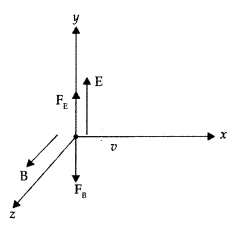
Question 26.
A charge q of mass m is moving with a velocity of v, at right
angles to a uniform magnetic field B. Deduce the expression for the radius of
the circular path it describes. (Comptt. Delhi 2015)
Answer:
Force
experienced by charged particle in magnetic field.![]()
As v and B are perpendicular, F = qvB
This force is
perpendicular to the direction of velocity and hence acts as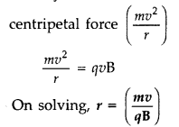
Question 27.
A proton and an alpha particle having the same kinetic energy
are, in turn, passed through a region of uniform magnetic field, acting normal
to the plane of the paper and travel in circular paths. Deduce the ratio of the
radii of the circular paths described by them. (Comptt. Delhi 2015)
Answer: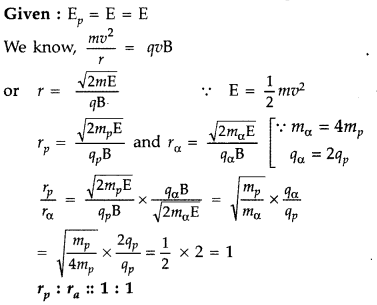
Question 28.
A charged particle having a charge q is moving with a speed of
v along the X-axis. It enters a region of space where the electric field is
\(\overrightarrow{\boldsymbol{E}}(\boldsymbol{E} \hat{\boldsymbol{j}})\) and a
magnetic field \(\vec{B}\) are both present. The particle, on emerging from the
region, is observed to be moving, along the X-axis only. Obtain an expression
for the magnitude of \(\vec{B}\) in terms of v and E. Give the direction of
\(\vec{B}\).
Answer:
Since the particle continues to move along the
X-axis, therefore, the magnetic force acting on it should be completely balanced
by the electric force. Since the electric force acts along the Y-axis,
therefore, the magnetic force must be along the Z-axis.
Thus is equilibrium q
E = B q v or v = E/B
Question 29.
A stream of electrons traveling with speed v m s-1
at right angles to a uniform magnetic field ‘B’ is reflected in a circular path
of radius ‘r’ . Prove that \(\frac{e}{m}=\frac{v}{r B}\)
Answer:
Let a
stream of electrons be traveling with speed v at right angles to a uniform
magnetic field B then force due to magnetic field provides the required
centripetal force which deflects the electron beam along a circular path of
radius ‘r’ such that
Bev = \(\frac{m v^{2}}{r}\)
or
\(\frac{e}{m}=\frac{v}{r B}\)
where e = electronic charge and m = mass of the
electron.
Question 30.
Which one of the two, an ammeter or a milliammeter, has a
higher resistance and why?
Answer:
The shunt resistance connected to
convert a galvanometer into an ammeter or a milliammeter is given by the
expression S = \(\frac{I_{g} G}{I-l_{g}}\) where S is shunt resistance, G
galvanometer resistance, l total current through G and S, and lg
galvanometer current. In the case of milliammeter, l is small.
Therefore Smilliammeter > Sammeter . Hence the resistance of a milliammeter is greater than that of an ammeter.
Question 31.
A straight wire of length L carrying a current l stays
suspended horizontally in mid-air in a region where there is a uniform magnetic
field \(\vec{B}\). The linear mass density of the wire is l. Obtain the
magnitude and direction of the magnetic field.
Answer:
The magnetic force
acting on the straight wire balances the weight of the wire.
Therefore, in
equilibrium we have Mg = BIL, here M =
L l, therefore we have L l g = BlL or B = l/ l g
This field acts vertically
upwards.
Question 32.
In the figure below, the straight wire AB Is fixed while the
loop Is free to move under the influence of the electric currents flowing in
them. In which direction does the loop begin to move? Give a reason for your
answer.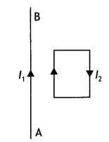
Answer:
The loop moves towards the straight wire AB. In the loop in the side
nearer to the wire AB current l2 is in the same direction as
l1 and hence attractive force acts. However, on the side farther away
from the wire AB current l2 is in the opposite direction and the
force is repulsive. But as the magnitude of attractive force is greater than the
repulsive force, the net force is attractive in nature and hence, the loop moves
towards the wire AB.
Question 33.
A coil of ‘N’ turns and radius ‘R’ carries a current ‘l’. It
is unwound and rewound to make a square coil of side ‘a’ having the same number
of turns (N). Keeping the current ‘l’ same, find the ratio of the magnetic
moments of the square coil and the circular coil. (CBSE Delhi 2013C)
Answer:
The magnetic moment of a current loop is given by the relation M =
nlA
For the circular loop Mc = NlπR² …(1)
Now when the coil is unwound and rewound to make a square coil, then
2 πR
= 4a or a = πR/2
Hence magnetic moment of the square coil is
Ms = Nl a² = Nl
(πR/2)² = Nl π²R²/4 …(2)
From (1) and (2) we have
\(\frac{M_{S}}{M_{C}}=\frac{N l \pi^{2} R^{2} /
4}{N l \pi R^{2}}=\frac{\pi}{4}\)
Question 34.
Write the expression for Lorentz magnetic force on a particle
of charge ‘q’ moving with velocity v in a magnetic field B. Show that no work is
done by this force on the charged particle. (CBSE Al 2011)
Answer:
The
expression is \(\vec{F}\) = q(\(\vec{v}\) × \(\vec{B}\)). This force always acts
perpendicular to the direction of motion of the charged particle. Therefore the
angle between \(\vec{F}\) and \(\vec{r}\) is 90°. Hence work done is W =
\(\vec{F}\). r = Fr cos 90° = 0
Question 35.
(a) State Biot-Savart law in vector form expressing the
magnetic field due to an element \(\vec{dl}\) carrying current l at a distance
\(\vec{r}\) from the element.
Answer:
It states that for a small current
element dl the magnetic field at a distance r is given by
\(\overrightarrow{d
B}=\frac{\mu_{0}}{4 \pi} \frac{I \overline{(d L} \times \hat{r})}{r^{2}}\).
(b) Write the expression for the magnitude of the magnetic field at the
center of a circular loop of radius r carrying a steady current l. Draw the
field lines due to the current loop. (CBSE Al 2014C)
Answer:
The magnetic
field at the center of a circular loop is given by
B = \(\frac{\mu_{0} l}{2
r}\)
The field lines are as shown.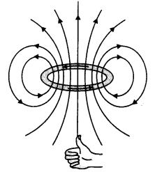
Question 36.
Draw the magnetic field lines due to current passing through a
long solenoid. Use Ampere’s circuital law, to obtain the expression for the
magnetic field due to the current l in a long solenoid having n number of turns
per unit length. (CBSE Delhi 2014C)
Answer:
The diagram is as
shown.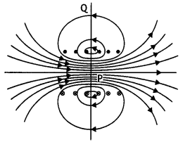
Consider a rectangular path abed of length L as shown in the figure below. Let
us apply Ampere’s circuital law to this rectangular path so that we have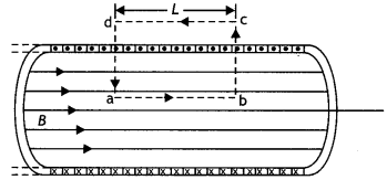
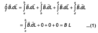
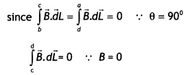
But by Ampere’s circuital law we have
\(\oint \vec{B} \cdot \vec{d} L\) =
μ0Nl = μ0(nL)l …(2)
From equations (1) and (2) we have
BL = μ0nLl
or
B =
μ0 n l
But n = N/L, therefore we have
B = μ0 \(\frac{N l}{L}\)
This gives the value of a magnetic field inside a solenoid.
Question 37.
(a) Why do we use a shunt to convert a galvanometer into an
ammeter?
Answer:
Since an ammeter is an instrument used to measure the
current in the circuit, so it has to be connected in series in the circuit to
measure the whole current. Hence its resistance must below. A low shunt
resistance makes it suitable for measuring current.
(b) A galvanometer of resistance 15 Ω shows a full-scale deflection on the
meter scale for a current of 6 mA. Calculate the value of the shunt resistance
required to convert the galvanometer into an ammeter of range 0-6 A. (CBSE
2019C)
Answer:
Given G = 15 Ω, lg = 6 mA = 6 ×
10-3 A, l = 6 A, S = ?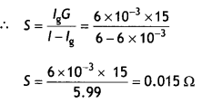
Question 38.
An electron beam projected along + X-axis experiences a force
due to a magnetic field along the + Y-axis. What is the direction of the
magnetic field?
Answer:
The direction of the magnetic field is along
Z-axis. This is because the direction of motion, the magnetic field, and the
force are perpendicular to one other as an electron carries a negative
charge.
Question 39.
A current is set up in a long copper pipe. Is there a
magnetic field
(i) inside,
Answer:
There is no magnetic field inside
the pipe.
(ii) outside the pipe?
Answer:
There is a magnetic field outside the
pipe.
Question 40.
Which one of the following will experience a maximum force,
when projected with the same velocity V perpendicular to the magnetic field (i)
alpha particle and (ii) beta particle?
Answer:
The force experienced by a
charged particle is given by the expression F = B q v. Since an alpha particle
has a moving charge than the beta particle, therefore the alpha particle will
experience more force.
Question 41.
An electron and a proton moving parallel to each other in the
same direction with equal momenta enter into a uniform magnetic field which is
at right angles to their velocities. Trace their trajectories in the magnetic
field.
Answer:
Because both electron and proton have the same charge and
momentum, therefore they will describe circles of equal radii as shown.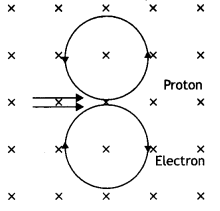
Question 42.
Is the steady electric current the only source of the magnetic
field? Justify your answer. (CBSE Delhi 2013C)
Answer:
No, the magnetic
field is also produced by alternating current.
Question 42 a.
A deuteron and an alpha particle having the same momentum is
in turn allowed to pass through a magnetic field B, acting normal to the
direction of motion of the particles. Calculate the ratio of the radii of the
circular paths described by them. (CBSE Delhi 2019)
Answer:
Pd
= Pα
Now r = \(\frac{mv}{Bq}\) ⇒ r ∝ \(\frac{1}{q}\)
Therefore, \(\frac{r_{d}}{r_{\alpha}}=\frac{q_{\alpha}}{q_{d}}=\frac{2 e}{e}\) = 2
Question 43.
Two wires of equal length are bent in the form of two loops.
One of the loops is square-shaped and the other is circular. These are suspended
in a uniform magnetic field and the same current is passed through them. Which
loop will experience a greater torque? Give reasons.
Answer:
Torque
experienced by a current-carrying loop placed in a uniform magnetic field is
given by the expression τ = BlnA. In other words, torque is directly
proportional to the area of the loop. Since a circular wire has more area than a
square wire for the same dimension, therefore the circular wire experiences more
torque than the square wire.
Question 44.
Which one of the following will have a minimum frequency of
revolution, when projected with the same velocity v perpendicular to the
magnetic field B: (i) alpha particle and (ii) beta particle?
Answer:
The
frequency of revolution of a charged particle in a magnetic field is given by
Bq
v = \(\frac{Bq}{2πm}\).
The ratio of q/m for an alpha particle is less than that for a beta particle; therefore, the alpha particle will have a minimum frequency of revolution.
Question 45.
Using the concept of force between two infinitely long
parallel current-carrying conductors, define one ampere of current. (CBSE AI
2014)
Answer:
One ampere is that much current which when flowing through
each of the two infinitely long straight conductors held 1 meter apart in space,
produce a force of F= 2 × 10⁻⁷ N per meter of their length.
Question 46.
(a) Write the expression for the force \(\vec{F}\) , acting
on a charged particle of charge ‘q’, moving with a velocity v in the presence of
both electric field \(\vec{E}\) and magnetic field \(\vec{B}\) . Obtain the
condition under which the particle moves undeflected through the fields.
Answer:
(a) The required expression is \(\vec{F}=q \vec{E}+q(\vec{v} \times
\vec{B})\)
The particle will move undeflected if the force acting on it due to the electric field balances the force acting on it due to the magnetic field. Thus qE = Bqv or v=E/B
(b) A rectangular loop of size l × b carrying a steady current I is placed in
a uniform magnetic field \(\vec{B}\) . Prove that the torque τ acting on the
loop is given by \(\vec{τ}\) = \(\vec{m}\) × \(\vec{B}\) , where m is the
magnetic moment of the loop. (CBSE AI 2012, Delhi 2013)
Answer:
The figure
below shows a rectangular loop of wire with length ‘a’ and breadth ‘b’. A line
perpendicular to the plane of the loop (i.e. a normal to the plane) makes an
angle Φ with the direction of the magnetic field B, and the loop carries a
current / as shown. Let the forces acting on the various sides of the loop be
\(\vec{F}_{1}\), \(\vec{F}_{2}\), \(\vec{F}_{3}\) and \(\vec{F}_{4}\) as
shown.
It follows from the expression for the force experienced by a conductor in a
magnetic field that force on arm AB is
\(\vec{F}_{1}=I(\overrightarrow{\mathrm{AB}} \times \vec{B})\) …(1)
(in the
plane of the paper and is directed upwards as shown).
The force on arm CD is given by \(\vec{F}_{2}=l(\overrightarrow{\mathrm{CD}}
\times \vec{B})\) …(2)
(in the plane of the paper and is directed downwards
as shown.)
Since these two forces are equal and opposite and have the same line of action therefore they cancel out each other’s effect and their resultant effect on the coil is zero.
Now the force on arm BC is
\(\vec{F}_{3}=l(\overrightarrow{\mathrm{BC}}
\times \vec{B})\) …(3)
(acts perpendicular to the plane of the paper and is
directed outwards as shown) Finally the force on arm DA is
\(\vec{F}_{4}=I(\overrightarrow{\mathrm{DA}} \times \vec{B})\) …(4)
(acts
perpendicular to the plane of the paper and is directed inwards as shown in
figure).
Both forces F3 and F4 make an angle of 90° with the
direction of the magnetic field. Therefore, in magnitude, these forces are given
by
F3 = F4 = laB sin90° = laB …(5)
The lines of action of both these forces are perpendicular to the plane of
the paper. The two forces F3 and F4 lie along different lines and each give rise
to a torque about the X-axis. The two torques produce a resultant torque in + X
direction. The arm of the couple (perpendicular distance between the lines of
action of the two forces) from the figure below is given by
An arm of couple
= b Sin Φ …(6)
Therefore, by the definition of torque we have
Torque = either force × arm
of couple Using equations (5) and (6) we have
Torque = l B a × b Sin Φ
But
a b = A, area of the coil, therefore τ = l B A Sin Φ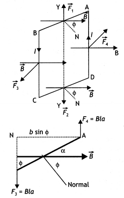
Question
47.
Show that a force that does no work must be a velocity-dependent force.
(NCERT Exemplar)
Answer:
We know that work is the dot product of force and
displacement, therefore
dW = \(\vec{F} \cdot d \vec{l}\) = 0
Or
dW =
\(\vec{F}\) .\(\vec{v}\)dt = 0
Or
\(\vec{F} \cdot \vec{v}\) = 0
Thus F must be velocity dependent which implies that the angle between F and v is 90°. If v changes direction then the direction of F should also change so that the above condition is satisfied.
Question 48.
Five long wires A, B, C, D, and E, each carrying current l is
arranged to form edges of a pentagonal prism as shown in the figure. Each
carries current out of the plane of the paper.
(a) What will be magnetic
induction at a point on axis 0? Axis is at a distance R from each wire.
(b)
What will be the field if the current in one of the wires (say A) is switched
off?
(c) What if the current in one of the wires (say) A is reversed? (NCERT
Exemplar)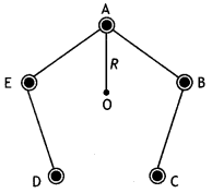
Answer:
(a) Zero Mn I
(b) \(\frac{\mu_{0}}{2 \pi} \frac{1}{R}\)
perpendicular to AO towards left
(c) \(\frac{\mu_{0}}{\pi} \frac{1}{R}\)
perpendicular to AO towards left
Question 49.
A circular coil of 200 turns and radius 10 cm is placed in a
uniform magnetic field of 0.5 T, normal to the plane of the coil. If the current
in the coil is 3.0 A, calculate the
(a) total torque on the coil.
(b)
total force on the coil.
(c) average force on each electron in the coil, due
to the magnetic field.
Assume the area of cross-section of the wire to be
10-5 m2 and the free electron density is
1029/m3. (All India 2015)
Answer:
(b) As the forces on different parts of the coil appears in
pairs, equal in magnitude and opposite in direction, net force on the coil is
zero.i.e., F = 0
Question 50.
An electron moves around the nucleus in a hydrogen atom of
radius 0.51 A, with a velocity of 2 × 10⁵ m/s. Calculate the
following :
(i) the equivalent current due to orbital motion of electron
(ii) the magnetic field produced at the centre of the nucleus
(iii) the
magnetic moment associated with the electron. (All India 2015)
Answer: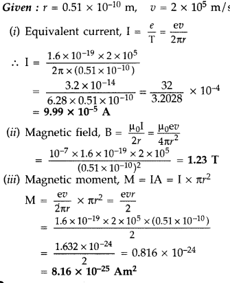
Question 51.
Derive the expression for force per unit length between two
long straight parallel current carrying conductors. Hence define one ampere.
(Delhi 2015)
Answer:
Consider two infinitely long parallel conductors
carrying current I1 and I2 in the same direction.
Let d
be the distance of separation between these two conductors.
Hence, force is attractive in nature.
Ampere : Ampere is
that current which is if maintained in two infinitely long parallel conductors
of negligible cross-sectional area separated by 1 metre in vacuum causes a force
of 2 × 10⁻⁷ N on each metre of the other wire.
Then current
flowing is 1A

Question 52.
Explain the principle and working of a cyclotron with the
help of a schematic diagram. Write the expression for cyclotron frequency.
(Delhi 2015)
Answer:
Cyclotron :
Principle : When a positively charged
particle is made to move again and again in a high frequency electric field, it
gets accelerated and acquires sufficiently large amount of energy.
Working : Suppose a positive ion, say a proton, enters the
gap between the two dees and finds dee D1 to be negative. It gets
accelerated towards dee D1. As it enters the dee D1, it
does not experience any electric field due to shielding
effect of the
metallic dee. The perpendicular magnetic field throws it into a circular
path.
At the instant the proton comes out of dee D1. It finds dee
D1 positive and dee D2 negative. It now gets accelerated
towards dee D2. It moves faster through dee D2 describing
a larger semicircle than before. Thus if the frequency of the applied voltage is
kept exactly the same as the frequency of the revolution of the proton, then
everytime the proton reaches the gap between the two dees, the electric field is
reversed and proton receives a push and finally it acquires very high energy.
This proton follows a spiral path. The accelerated proton is ejected through a
window by a deflecting voltage and hits the target.
Centripetal force is
provided by magnetic field to charged particle to move in a circular
back.
Question 53.
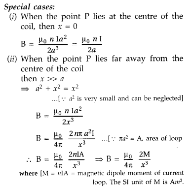
Find the magnetic field at a point on the axis of a circular
coil carrying current and hence find the magnetic field at the centre of the
circular coil carrying current.
Answer:
Magnetic field at a point on the
axis of a circular coil carrying current
Consider a circular coil of radius
‘a’ with centre ‘O’, carrying current I. Its plane is perpendicular to the plane
of the loop. Suppose P is any point on the axis of the circular coil at a
distance x from the centre, such that
OP = x
Consider two small elements
of length dl at C and D at diametrically opposite current elements of the
coil
PC = PD = r = \(\sqrt{a^{2}+x^{2}}\)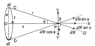
According to Biot Savart’s law, the magnitude of magnetic
field at P due to current element dl at C is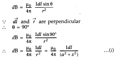
The direction of \(\overrightarrow{d
\overrightarrow{\mathrm{B}}}\) is perpendicular to \(\vec{r}\) in the plane
paper i.e., along PQ.
Similarly, the magnitude of magnetic field at P due to
current element dl at D is![]()
Its direction is along PQ’
From (i) an (ii), we get, dB =
dB’ = \(\frac{\mu_{0}}{4 \pi} \frac{\mathrm{I} d
l}{\left(a^{2}+x^{2}\right)}\)
components :
(i) dB cos ϕ along PY and dB’ sin ϕ along
PX
(ii) dB cos ϕ along PY and dB’ sin ϕ along PX
Since the components of
the magnetic field along Y-axis are equal and opposite and cancel each other,
the components along X-axis are in the same direction and are added up.
Hence
the total magnetic field at point P is,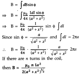
Question 54.
Deduce the expression for the magnetic dipole moment of an
electron orbiting around the central nucleus. (All India 2010)
Answer:
Consider an electron revolving around the nucleus of an atom. Electron is in
uniform circular motion around the nucleus of charge + Ze. This constitutes a
current.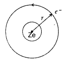
![]()
If ‘r’ is orbital radius of the electron and ‘V’ is orbital
speed, then the time period is![]()
Now putting the value of T in (i), we get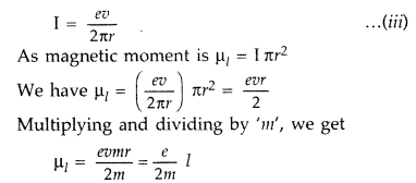
…where [Z is angular momentum of the electron.
According
to Bohr hypothesis angular momentum we can have discrete values only.![]()
Question 55.
A long straight wire of a circular cross-section of radius
‘a’ carries a steady current ‘I’. The current is uniformly distributed across
the cross-section. Apply Ampere’s circuital law to calculate the magnetic field
at a point V in the region for
(i) r < a and (ii) r > a.
Answer:
Consider an infinite long thick wire of radius V with axis XY. Let I be the
current flowing through the wire.
When the point P lies outside the wire
: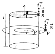
Let r be the perpendicular distance of point P from the axis
of the cylinder, where r > a.
Here \(\overrightarrow{\mathrm{B}}\) and d
\(\overrightarrow{\mathrm{l}}\) are acting in the same direction.
Applying
Ampere’s circuital law, we have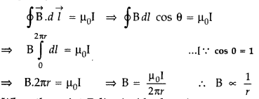
When the point P lies inside the wire :
Here r ≤ a. We
have two possibilities:
According to Ampere circuital law,
(i) “Whenever
the current floras only through the surface of the wire, B = 0 as current in the
closed path will be zero.”
(ii) “Wherever in the case when current is
uniformly distributed through the cross-section of conductor, current through
the closed path will be :
I’ = Current per unit area of the wire × area of
the circle of radius r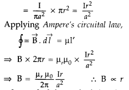
Question 56.
State the underlying principle of working of a moving coil
galvanometer. Write two reasons why a galvanometer can not be used as such to
measure current in a given circuit. Name any two factors on which the current
sensitivity of a galvanometer depends. (Delhi 2010)
Answer:
(i) Moving
coil galvanometer works on the principle of a torque experienced by a current
carrying coil placed in a magnetic field, whose magnitude is a function of
current passing through the coil.
(ii) The galvanometer cannot be used to
measure the value of the current in a given circuit due to the following two
reasons:
(a) Galvanometer is a very sensitive device. It gives a full scale
deflection for a small value of current.
(b) The galvanometer has to be
connected in series for measuring currents and as it has a large resistance,
this will change the value of the current in the circuit.
(iii)![]()
It depends on the number of turns N of the coil, torsion
constant and the area A of the coil.
Question 57.
Write the expression for the magnetic moment
(\(\overrightarrow{\mathbf{M}}\)) due to a planar square loop of side ‘l’
carrying a steady current I in a vector form. In the given figure this loop is
placed in a horizontal plane near a long straight conductor carrying a steady
current I, at a distance l as shown. Give reasons to explain that the loop will
experience a net force but no torque. Write the expression for this force acting
on the loop. (Delhi 2010)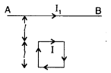
Answer:
(i) The magnetic moment
\((\overrightarrow{\mathrm{M}})\) due to a planar square loop of side ‘l’
carrying a steady current I in a vector form is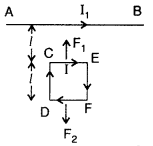
![]()
(ii) CE will be attracted towards AB with a force
F1 given by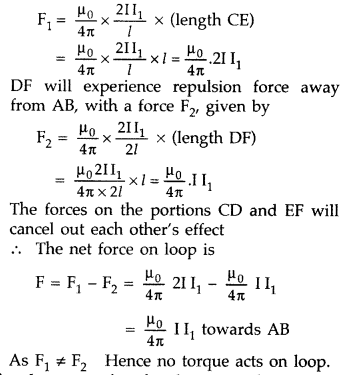
Question 58.
Write the expression for the magnetic moment
(\(\overrightarrow{\mathbf{M}}\)) due to a planar square loop of side ‘l’
carrying a steady current I in a vector form. In the given figure this loop is
placed in a horizontal plane near a long straight conductor carrying a steady
current I, at a distance l as shown. Give reasons to explain that the loop will
experience a net force but no torque. Write the expression for this force acting
on the loop. (Delhi 2010)
Answer:
(i) The magnetic moment
\((\overrightarrow{\mathrm{M}})\) due to a planar square loop of side ‘l’
carrying a steady current I in a vector form is
![]()
(ii) CE will be attracted towards AB with a force
F1 given by
Question 59.
A rectangular loop of wire of size 4 cm × 10 cm carries a
steady current of 2 A. A straight long wire carrying 5 A current is kept near
the loop as shown. If the loop and the wire are coplanar, find
(i) the torque
acting on the loop and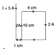
(ii) the magnitude and direction of the force on the loop due
to the current carrying wire. (Delhi 2012)
Answer:
τ = IAB sin θ => τ =
IAB sin θ (as θ = 0)![]()
(ii) Force acting on the loop on |F|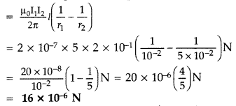
Direction : Towards conductor/Attractive Net force on the
loop will act towards the long conductor (attractive) if the current in its
closer side is in the same direction as the current in the long conductor,
otherwise it will be repulsive.
Question 60.
A rectangular loop of wire of size 2 cm × 5 cm carries a
steady current of 1 A. A straight long wire carrying 4 A current is kept near
the loop as shown in the figure.
If the loop and the wire are coplanar,
find
(i) the torque acting on the loop and
(ii) the magnitude and
direction of the force on the loop due to the current carrying wire. (Delhi
2010)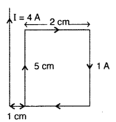
Answer:
(i) τ (Torque on the loop) = MB sin θ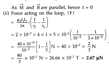
Direction : Towards the conductor/Attractive
Net force on the loop will
act towards the long conductor (attractive) if the current in its closer side is
in the same direction as the
current in the long conductor, otherwise it will
be repulsive.
Question 61.
Two identical coils, each of radius ‘R’ and number of turns
‘N’ are lying in perpendicular planes such that their centres coincide. Find the
magnitude and direction of the resultant magnetic field at the centre of the
coils, if they are carrying currents ‘I’ and √3I respectively.
(Comptt. Delhi
2010)
Answer: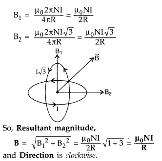
Question 62.
Two identical coils, each of radius ‘R’ and number of turns
‘N’ are lying in perpendicular planes such that their centres coincide. Find the
magnitude and direction of the resultant magnetic field at the centre of the
coils, if they are carrying currents ‘I’ and √2I respectively.
(Comptt. Delhi
2010)
Answer: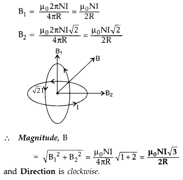
Question 63.
Figure shows a rectangular loop conducting PQRS in which the
arm PQ is free to move. A uniform magnetic field acts in the direction
perpendicular to the plane of the loop. Arm PQ is moved with a velocity v
towards the arm RS. Assuming that the arms QR, RS and SP have negligible
resistances and the moving arm PQ has the resistance r, obtain the expression
for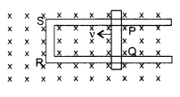
(i) the current in the loop
(ii) the force and
(iii)
the power required to move the arm PQ. (Delhi 2010)
Answer:
Let the
magnetic field acting on the loop be B and length of the rod PQ be l
The
induced e.m.f. ε = Blv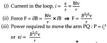
Question 64.
A rectangular conductor LMNO is placed in a uniform magnetic
field of 0.5 T. The field is directed perpendicular to the plane of the
conductor. When the arm MN of length of 20 cm is moved towards left with a
velocity of 10 ms-1, calculate the emf induced in the arm. Given the
resistance of the arm to be 5Ω (assuming that other arms are of negligible
resistance) find the value of the current in the arm. (All India 2010)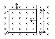
Answer: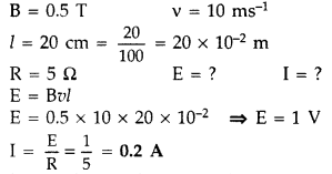
Question 65.
A wire AB is carrying a steady current of 12A and is lying on
the table. Another wire CD carrying 5A is held directly above AB at a height of
1 mm. Find the mass per unit length of the wire CD so that it remains suspended
at its position when left free. Give the direction of the current flowing in CD
with respect to that in AB. [Take the value of g = 10 ms-2] (All
India 2010)
Answer:
Given :
Current in the wire AB (I1) = 12
A,
Current in wire CD (I2) = 5 A
Separation between two wires
(d) = 1 mm
= 10-3 m
Let ‘m’ be the mass of wire CD of length
(L),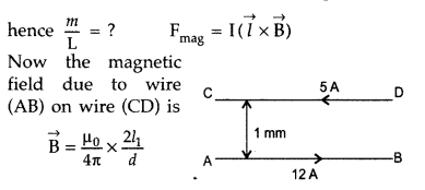
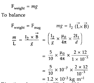
Direction of current in CD should be opposite to that of
AB.
Question 66.
A wire AB is carrying a steady current of 10 A and is lying
on the table. Another wire CD carrying 6 A is held directly above AB at a height
of 2 mm. Find the mass per unit length of the wire CD so that it remains
suspended at its position when left free. Give the direction of the current
flowing in CD with respect to that in AB. [Take the value of g = 10
ms-2] (All India 2010)
Answer:
Let AB has current in +ve
x-direction
(I1) Current in wire AB = 10 A,
(I2)
Current in wire CD = 6 A
Separation between the two wires = 2 mm
= 2 ×
10-3m
To keep the wire CD suspended in its vertical position when
left free. For this magnetic force on CD due to AB should balance mg due to its
own weight.
Let m be the mass of the wire CD and L be its length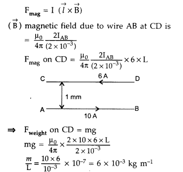
Direction of current in CD should be opposite to that AB.
Question 67.
(a) Define the current sensitivity of a galvanometer.
(b)
The coil area of a galvanometer is 16 × 10-4 m2. It
consists of 200 turns of a wire and is in a magnetic field of 0.2 T. The
restoring torque constant of the suspension fibre is 10-6 Nm per
degree. Assuming the magnetic field to be radial, calculate the maximum current
that can be measured by the galva-nometer if the scale can accommodate 30°
deflection. (Comptt. All India 2010)
Answer:
Sensitivity of a
galvanometer: A galvanometer is said to be sensitive, if it gives a large
deflection, even when a small current passes through it.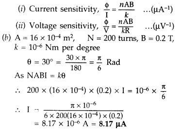
Question 68.
(a) State Ampere’s circuital law, expressing it in the
integral form.
(b) Two long coaxial insulated solenoids, S1 and
S2 of equal lengths are wound one over the other as shown in the
figure. A steady current “I” flows through the inner solenoid S1 to
the other end B, which is connected to the outer solenoid S2 through
which the same current “l” flows in the opposite direction so as to come out at
end A. If n1 and n2 are the number of turns per unit
length, find the magnitude and direction of the net magnetic field at a
point
(i) inside on the axis and
(ii) outside the combined system. (Delhi
2014)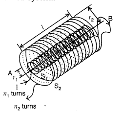
Answer:
(a) According to Ampere’s Circuital law, the
magnetic field B is related to steady current![]()
(i) Inside the combined system : Magnetic field at a point on
the axis.
Using Ampere’s Circuital law, the magnetic field due to inner
solenoid S1 is given by![]()
Similarly due to outer solenoid S2,![]()
Since these two magnetic fields are opposite in
direction,![]()
in the upward direction.
(ii) Outside the combined system
: At such a point, magnetic field is zero, because corresponding turns of the
two halves of the solenoid produce equal and opposite magnetic fields.
Question 69.
Consider the motion of a charged particle of mass ‘m’ and
charge ‘q’ moving with velocity \(\vec{v}\) in a magnetic field \(\vec{B}\).
(a) If \(\vec{v}\) is perpendicular to \(\vec{B}\), show that it describes a
circular path having angular frequency ω = qB/m.
(b) If the velocity
\(\vec{v}\) has a component parallel to the magnetic field \(\vec{B}\), trace
the path described by the particle. Justify your answer. (Comptt. Delhi
2014)
Answer:
(a) When a charged particle with charge q moves inside a
magnetic field \(\overrightarrow{\mathrm{B}}\) with velocity v, it experiences a
force, which is given by
Here, \(\overrightarrow{\mathrm{v}}\) is perpendicular to
\(\overrightarrow{\mathrm{B}}\), \(\overrightarrow{\mathrm{F}}\) is the force on
the charged particle which acts as the centripetal force and makes it move along
a circular path.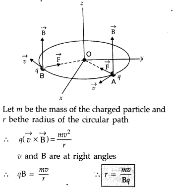
Let m be the mass of the charged particle and r be the radius
of the circular path.
Time period of circular motion of the charged particle
can be calculated as shown below: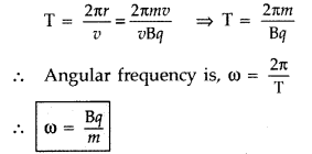
Therefore, the frequency of the revolution of the charged
particle is independent of the velocity or the energy of tire particle.
(b)
Principle : When a positively charged particle is made to move again and
again in a high frequency electric field, it gets accelerated and acquires
sufficiently large amount of energy.
Working : Suppose a positive ion, say a proton, enters the
gap between the two dees and finds dee D1 to be negative. It gets
accelerated towards dee D1. As it enters the dee D1, it
does not experience any electric field due to shielding effect of the metallic
dee. The perpendicular magnetic field throws it into a circular path.
At the instant the proton comes out of dee D1. It finds dee
D1 positive and dee D2 negative. It now gets accelerated
towards dee D2. It moves faster through dee D2 describing
a larger semicircle than
before. Thus if the frequency of the applied voltage
is kept exactly the same as the frequency of the revolution of the proton, then
everytime the proton reaches the gap between the two dees, the electric field is
reversed and proton receives a push and finally it acquires very high energy.
This proton follows a spiral path. The accelerated proton is ejected through a
window by a deflecting voltage and hits the target.
Centripetal force is
provided by magnetic field to charged particle to move in a circular
back.
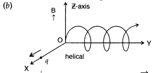
Justification : Component of velocity \(\vec{v}\), parallel to magnetic field, will make the particle move along the field.
Perpendicular component of velocity \(\vec{v}\) will cause the particle to move along a circular path in the plane perpendicular to the magnetic field Hence, the particle will follow a helical path, as shown above.
Question 70.
(a) Draw a schematic sketch of a moving coil galvanometer and
describe briefly its working.
(b) “Increasing the current sensitivity of a
galvanometer does not necessarily increase the voltage sensitivity.” Justify
this statement. (Comptt. Delhi 2014)
Answer:
(a)
Principle : “If a
current carrying coil is freely suspended/pivoted in a uniform magnetic field,
it experiences a deflecting torque.”
Working: As the pivoted coil is placed
in a radial magnetic field, hence on passing current I through it, a deflecting
torque acts on the coil which is given by, τ = NAIB![]()
The spring Sp attached to the coil provides the
counter torque and in equilibrium state balances the deflecting torque. If φ is
steady angular deflection then counter torque is kφ.
…where [k = torsional
constant of the spring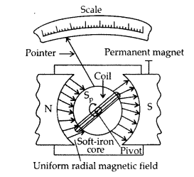
In equilibrium state,![]()
Thus, deflection is directly proportional to the current
flowing in the coil.
(a) (i) Uniform radial magnetic field. It keeps the
magnetic field line normal to the area vector of the coil.
(ii) Soft iron
core in galvanometer. The cylindrical soft iron core, when placed inside the
coil of a galvanometer, makes the magnetic field stronger and radial in the
space between it and pole pieces, such that whatever the position of the
rotation of the coil may be, the magnetic field is always parallel to its
plane.
(b) (i) Current sensitivity is defined as the deflection produced in
the galvanometer when unit current is passed through its coil.
(ii) Voltage sensitivity is defined as the deflection
produced in the galvanometer when unit voltage is applied across the coil of the
galvanometer.
…where [R = Resistance of the coil![]()
does not necessarily increase the voltage sensitivity. It may
be affected by the resistance used.
(b) Current sensitivity is defined as the deflection produced in the
galvanometer when unit current is passed through its coil.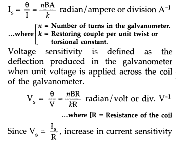
may not necessarily increase the voltage sensitivity. It may
be affected by the resistance used.
Question 71.
A uniform magnetic field \(\overrightarrow{\mathrm{B}}\) is
set up along the positive x-axis. A particle of charge ‘q’ and mass ‘m’ moving
with a velocity v enters the field at the origin in X-Y plane such that it has
velocity components both along and perpendicular to the magnetic field
\(\overrightarrow{\mathrm{B}}\). Trace, giving reason, the trajectory followed
by the particle. Find out the expression for the distance moved by the particle
along the magnetic field in one rotation. (All India 2014)
Answer:
Since
the velocity of the particle is inclined to x-axis, thererfore, the velocity has
a component along B, this component remains unchanged as the motion along the
magnetic field will not be affected by the magnetic field. The motion in a plane
perpendicular to B is as before a circular one, thereby producing a helical
motion, which is its trajectory.
If r is the radius of the circular path of a particle, then a force of
mv2/r, acts perpendicular to the path towards the centre of the
circle and is called the centripetal force. If the velocity v is perpendicular
to the magnetic field B, the magnetic force is perpendicular to both v and B and
acts like a centripetal force. It has a magnitude qvB. Equating the two
expressions (for centripetal force)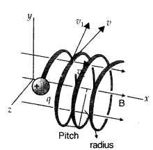
mv2/r = qvB, which gives r = mv/qB …(i) for the
radius of the circle described by the charged particle.![]()
There is a component of the velocity parallel to the magnetic
field (denoted by v11), it will make the particle move along the
field and the path of the particle would be a helical one.
The distance moved along the magnetic field in one rotation is called pitch
p.
Using equation (ii), we have![]()
Question 72.
Write the expression for the generalized form of Ampere’s
circuital law. Discuss its significance and describe briefly how the concept of
displacement current is explained through charging/discharging of a capacitor in
an electric circuit. (All India 2014)
Answer:
Maxwell’s displacement
current : According to Ampere’s circuital law, the magnetic field
\(\overrightarrow{\mathrm{B}}\) is related to steady current I as,![]()
Maxwell showed that this relation is logically inconsistent.
He accounted this inconsistency as follows :
Ampere’s circuital laic for loop C, gives
Loop C2 lies in the region between the
plates

which is logically inconsistent. So, Maxwell gave idea of
displacement current.
Thus displacement current is that current which comes into play in the region
in which the electric![]()
where [ID is displacement current and![]()
It is now called Ampere-Maxwell law. This is the
generalization of Ampere’s Circuital law.
Question 73.
(a) Why is the magnetic field radial in a moving coil
galvanometer? Explain how it is achieved.
(b) A galvanometer of resistance
‘G’ can be converted into a voltmeter of range (0 – V) volts by connecting a
resistance ‘R’ in series with it. How much resistance will be required to change
its range from 0 to V/2? (Comptt. All India 2014)
Answer:
(a) The magnetic
field in a moving coil galvanometer is made ‘radial’ to keep the magnetic field
‘normal’ to the area vector of the coil. It is done by taking the cylindrical
soft iron core. The torque acting on the coil is maximum (sin θ = 1, when, θ =
90°)
(b) Given : resistance of galvanomter = G Ω
Range of voltmeter
(RL) = (0 – V) volts
Resistance to be connected in parallel =
R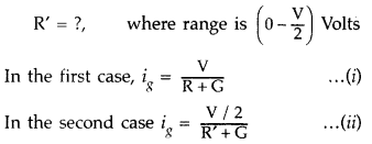
[ig is the maximum current which can flow through
galvanometer]
From equation (i) and (ii), on solving we get
Question 74.
A closely wound solenoid of 2000 turns and cross sectional
area 1.6 × 10⁻⁴ m2 carrying a current of 4.0 A is
suspended through its centre allowing it to turn in a horizontal plane. Find
(i) the magnetic moment associated with the solenoid,
(ii) magnitude and
direction of the torque on the solenoid if a horizontal magnetic field of 7.5 ×
10-2 T is set up at an angle of 30° with the axis of the solenoid.
(Comptt. All India 2014)
Answer: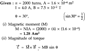

(iii) Direction of torque is perpendicular to both the planes
of the solenoid and the magnetic field.
Question 75.
(a) Write the expression for the magnetic force acting on a
charged particle moving with velocity v in the presence of magnetic field B.
(b) A neutron, an electron and an alpha particle moving with equal velocities,
enter a uniform magnetic field going into the plane of the paper as shown. Trace
their paths in the field and justify your answer. (Delhi 2016)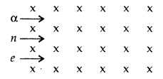
Answer:
(a) Expression for magnetic force :
(b) Justification : Direction of force experienced by 01 the
particle will be n according to Fleming’s Left hand rule.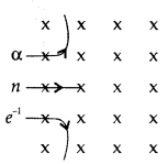
Question 76.
Two long straight parallel conductors carry steady current
I1 and I2 separated by a distance d. If the currents are
flowing in the same direction, show how the magnetic field set up in one
produces an attractive force on the other. Obtain the expression for this force.
Hence define one ampere. (Delhi 2014)
Answer:
Consider two infinitely long
parallel conductors carrying current I1 and I2 in the same
direction.
Let d be the distance of separation between these two
conductors.
Hence, force is attractive in nature.
Ampere : Ampere is
that current which is if maintained in two infinitely long parallel conductors
of negligible cross-sectional area separated by 1 metre in vacuum causes a force
of 2 × 10⁻⁷ N on each metre of the other wire.
Then current
flowing is 1A

Question 77.
Use Biot-Savart law to derive the expression for the magnetic
field on the axis of a current carrying circular loop of radius R.
Draw the
magnetic field lines due to a circular . wire carrying current I. (All India
2014)
Answer:
(i) According to Biot-Savart’s law, “magnetic field acting
at a particular point due to current carrying element is proportional to the
division of cross product of current element and position vector of point where
the field is to be calculated from the current element to the cube of the
distance between current element and the point where the field is to be
calculated”.

Magnetic field on the axis of circular current loop :
As in a special case we may obtain the field at the centre of
the loop. Here x = 0, and we obtain![]()
In a current loop, both the opposite faces behave as opposite
poles, making it a magnetic dipole. One side of the current carrying coil
behaves like the N-pole and the other side as the S-pole of a magnet.
(ii)
(a) Magnetic field lines :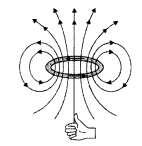
(b) Moving coil galvanometer. It is a device used for the
detection and measurement of small electric current.
Principle. The working
is based on the fact that a current carrying coil suspended in a magnetic field
experiences a torque.
Construction. It consists of a coil having a large
number of turns of insulated copper wire wound on a metallic frame. The coil is
suspended by means of a phosphor-bronze strip and is surrounded by a horse-shoe
magnet NS. A hair spring is attached to lower end of the coil. The other end of
the spring is attached to the scale through a pointer.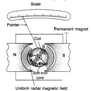
Working. When current is passed, say along ABCD, the couple acts on it. Since the plane remains always parallel to the magnetic field in all positions of the coil (radial field), the force on the vertical arms always remains perpendicular to the place of the coil.
Let, I be the current flowing through coil,
B be magnetic field supposed
to be uniform and always parallel to the coil, A be area of the coil
Deflecting torque acting on the coil is,
τ = nI BA sin 900
Due to deflecting torque, the coil rotates and suspension wire gets twisted.
A restoring torque is set up in the suspension fibre. If <|) is angle through
which the coil rotates and k is the restoring torque per unit angular twist,
then restoring torque, τ = kϕ
In equilibrium,
Deflecting torque =
Restoring torque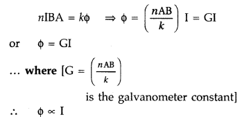
This provide a linear scale for the galvanometer.
Function
of a radial magnetic field : Radial magnetic field being normal in all
directions is formed to get maximum torque.
Function of Soft iron core, which
not only makes the field radial but also increases the strength of the magnetic
field.
(c) One uses a shunt resistance in parallel with the galvanometer, so
that most of the current passes through the shunt. In the case of a voltmeter, a
resistance of large value is used in series because it must draw a very small
current, otherwise the voltage measurement will disturb the original set up by
an amount which is very large.
Question 78.
Three long straight parallel wires are kept as shown in the
figure. The wire (3) carries a current I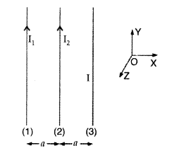
(i) The direction of flow of current I in wire (3), is such
that the net force, on wire (1), due to the other two wires, is zero.
(ii) By
reversing the direction of I, the net force, on wire (2), due to the other two
wires, becomes zero. What will be the directions of current I, in the two cases?
Also obtain the relation between the magnitudes of currents I1
I2 and I.
Answer: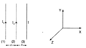
(i) Net force experienced by wire (1) can be zero only, when
the current in wire (3) flows along – \(\hat{\mathrm{j}}\) i.e. downwards, it
means that the forces acting on wire (1) due to wire (3) and wire (2) are equal
and opposite.
(ii) When direction of current in wire (3) is reversed then
current should be along + \(\hat{\mathrm{j}}\) i.e. upwards.
For this case
net force on wire (2) becomes zero, which means that the forces due to wire (1)
and wire (3) are equal and opposite.
Question 79.
A circular coil, having 100 turns of wire, of radius (nearly)
20 cm each, lies in the XY plane with its centre at the origin of co-ordinates.
Find the magnetic field, at the point (0, 0, 20√3 cm), when this coil carries a
current of (Comptt. Delhi 2016)
Answer: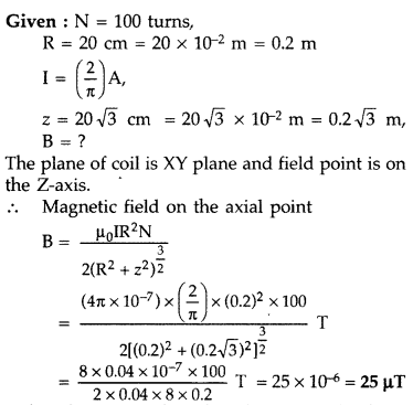
Question 80.
Write the expression for the magnetic force
\(\overrightarrow{\mathbf{F}}\) acting on a charged particle q moving with
velocity \(\overrightarrow{\mathbf{F}}\) in the presence of the magnetic field
\(\overrightarrow{\mathbf{B}}\) in a vector form. Show that no work is done and
no change in the magnitude of the velocity of the particle is produced by this
force. Hence define the unit of magnetic field. (Comptt. All India 2016)
Answer:
(i) The required expression is
\([latex]\overrightarrow{\mathbf{F}}=q(\vec{v} \times
\overrightarrow{\mathbf{B}})\)
(ii) The magnetic force, at all instants, is,
therefore, perpendicular to the instantaneous direction of \(\vec{v}\), which is
also the instantaneous direction of displacement (\(\overrightarrow{d s}\)).
Since, \(\overrightarrow{\mathrm{F}}\) is perpendicular to (\(\overrightarrow{d
s}\)), at all instants, work done \((=\overrightarrow{\mathrm{F}} \cdot
\overrightarrow{d s})\) is zero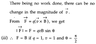
Hence, the magnetic field \(\overrightarrow{\mathrm{B}}\), at
a point equals one tesla if a charge of one coulomb, moving with a velocity
1/sec, along a direction perpendicular to the direction of
\(\overrightarrow{\mathrm{B}}\), experience a force of one newton.
Question 81.
A long straight wire, of circular cross section (radius = a)
carries a current I which is uniformly distributed across the cross section of
the wire.
Use Ampere’s circuital law to calculate the magnetic field B(r),
due to this wire, at a point distance r < a and r > a from its axis. Draw
a graph showing the dependence of B(r) on r. (Comptt. All India 2016)
Answer: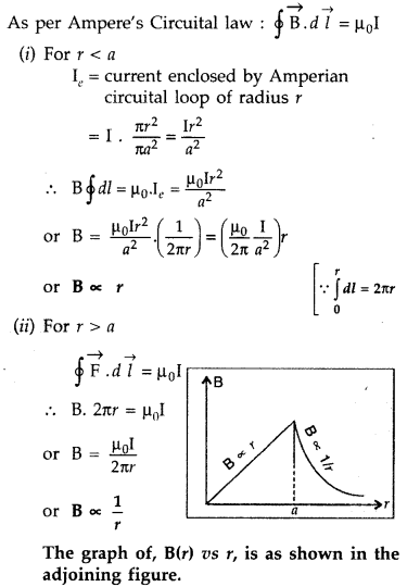
Question 82.
Derive the expression for the torque τ acting on a
rectangular current loop of area A placed in a uniform magnetic field B. Show
that \(\vec{\tau}=\vec{m} \times \overrightarrow{\mathbf{B}}\) where \(\vec{m}\)
is the magnetic moment of the current loop given by
\(\vec{m}=\overrightarrow{\mathbf{I}} \overrightarrow{\mathbf{A}}\). (Comptt.
All India)
Answer:
(a) Torque on a rectangular current loop in a uniform
magnetic field:
Let I = current through the coil
a, b – sides of the
rectangular loop
A = ab = area of the loop
n = Number of turns in the
loop
B = Magnetic field
θ = angle between magnetic field
\(\overrightarrow{\mathrm{B}}\) and area vector
\(\overrightarrow{\mathrm{A}}\)
Force exerted on the arm DA inward
F1 = I b B
…[∵ F = ILB]
Force exerted on the arm BC outward
F2 = I b B ∴
F2 = F1
Thus net force on the loop is zero
∴ Two
equal and opposite forces form a couple which exerts a torque
∴ Magnitude of
the torque on the loop is,
If loop has n turns then M = n I A
∴ τ = nIAB sin
θ
When θ = 90° then \(\tau_{\max }=n I A B\)
When θ = 0° then τ = 0
(b)
Since the momentum and the charge on both the proton and deutron are the same,
the particle will follow a circular path with radius 1:1.
Question 83.
(i) Obtain the expression for the cyclotron frequency.
(ii) A deuteron and a proton are accelerated by the cyclotron. Can both be
accelerated with the same oscillator frequency? Give reason to justify your
answer. (Delhi 2017)
Answer:
(i) Expression for cyclotron frequency : The
magnetic field provides necessary centripetal force needed by the charged
particle to move in a circular path.
m = mass of the charged particle,
v =
velocity,
r = radius of the circular path
q = charge,
B = Magnetic
field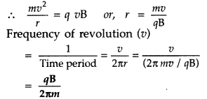
Therefore, the frequency of revolution is independent of
energy of the particle.
(ii) The mass of the two particles, i.e. deuteron and
proton, is different. Since cyclotron frequency depends inversely on the mass,
they cannot be accelerated by the same oscillator frequency.
Question 84.
Describe the working principle of a moving coil galvanometer.
Why is it necessary to use
(i) a radial magnetic field and
(ii) a
cylindrical soft iron core in a galvanometer? Write the expression for current
sensitivity of the galvanometer.
Can a galvanometer as such be used for
measuring the current? Explain. (Delhi 2017)
Answer:
Principle : “If a
current carrying coil is freely suspended/pivoted in a uniform magnetic field,
it experiences a deflecting torque.”
Working: As the pivoted coil is placed
in a radial magnetic field, hence on passing current I through it, a deflecting
torque acts on the coil which is given by, τ = NAIB![]()
The spring Sp attached to the coil provides the
counter torque and in equilibrium state balances the deflecting torque. If φ is
steady angular deflection then counter torque is kφ.
…where [k = torsional
constant of the spring
In equilibrium state,![]()
Thus, deflection is directly proportional to the current
flowing in the coil.
(a) (i) Uniform radial magnetic field. It keeps the
magnetic field line normal to the area vector of the coil.
(ii) Soft iron
core in galvanometer. The cylindrical soft iron core, when placed inside the
coil of a galvanometer, makes the magnetic field stronger and radial in the
space between it and pole pieces, such that whatever the position of the
rotation of the coil may be, the magnetic field is always parallel to its
plane.
(b) (i) Current sensitivity is defined as the deflection produced in
the galvanometer when unit current is passed through its coil.
(ii) Voltage sensitivity is defined as the deflection
produced in the galvanometer when unit voltage is applied across the coil of the
galvanometer.
…where [R = Resistance of the coil![]()
does not necessarily increase the voltage sensitivity. It may
be affected by the resistance used.
No, the galvanometer cannot be used to
measure current. It can only detect current but cannot measure as it is not
calibrated. The galvanometer coil is likely to be damaged by currents in the
(mA/A) range.
Question 85.
An electron of mass me revolves around a nucleus
of charge +Ze. Show that it behaves like a tiny magnetic dipole. Hence prove
that the magnetic moment associated with it is expressed as
\(\vec{\mu}=-\frac{e}{2 m_{e}} \overrightarrow{\mathbf{L}}\) where L is the
orbital angular momentum of the electron. Give the significance of negative
sign. (Delhi 2017)
Answer:
(i) Electron, in circular motion around the
nucleus, constitutes a current loop which behaves like a tiny magnetic
dipole.
Current associated with the revolving electron :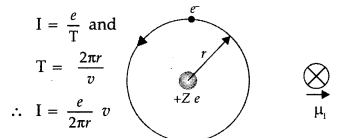
Magnetic moment of the loop, µ = IA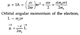
Negative sign signifies that the angular momentum of the
revolving electron is opposite in direction to the magnetic moment associated
with it.
Question 86.
(a) Write the expression for the force
\(\overrightarrow{\mathbf{F}}\) acting on a particle of mass m and charge q
moving with velocity \(\overrightarrow{\mathbf{v}}\) in a magnetic field
\(\overrightarrow{\mathbf{B}}\). Under what conditions will it move in
(i) a
circular path and
(ii) a helical path?
(b) Show that the kinetic energy of
the particle moving in magnetic field remains constant. (Delhi 2017)
Answer:![]()
(i) When velocity of charged particle and magnetic field are
perpendicular to each other, it will move in a circular path.
(ii) When
velocity is neither parallel nor perpendicular to the magnetic field, it will
move in helical path.
(b) The force experienced by the charged particle, is
perpendicular to the instantaneous velocity \(\vec{v}\), at all instants.
Hence the magnetic force cannot bring any change in the speed of the charged
particle. Since speed remains constant, the kinetic energy also stays
constant.
Question 87.
(a) State Biot-Savart law and express this law in vector
form.
(b) Two identical circular coils, P and Q each of radius R, carrying
currents 1 A and √3 A respectively, are placed concentrically and perpendicular
to each other lying in the XY and YZ planes. Find the magnitude and direction of
the net magnetic field at the centre of the coils. (All India 2017)
Answer:
(a) Biot-Savart law : It states that “the magnetic field dB due to a
current element d l at any point P is:
(i) directly proportional to current
dB ∝ I.
(ii) directly proportional to the length dl of the element \(d
\vec{B}\) ∝ dl.
(iii) directly proportional to sin θ, where θ is the angle
between d\(\overrightarrow{l}\) and \(\overrightarrow{r}\),
Therefore \(d
\vec{B}\) ∝ sin θ
(iv) inversely proportional to the square of the distance r
from the current element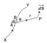
Combining (i), (ii), (iii) and (iv), we get
The direction of \(\overrightarrow{d \mathrm{B}}\) is
perpendicular to the plane of the vector d \(\vec{l}\) and \(\vec{r}\) given by
Right Handed Screw Rule.
(b) Consider a circular coil of radis r, carrying
current I. It consists of a large number of small current elements of length dl.
According to Biot-Savart law, magnetic field at the centre O due to current
element dl is,
Magnetic field due to all such current elements will point
into the plane of paper.
Hence total field at O is,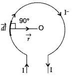
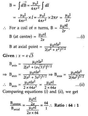
(b) Given : RP = RQ = R, Ip
= 1 A, IQ = √3 A
B = ? (Magnitude and direction)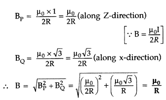
This net magnetic field B, is inclined to the field
BP, at an angle θ, where
Question 88.
Two identical loops P and Q each of radius 5 cm are lying in
perpendicular planes such that they have a common centre as shown in the figure.
Find the magnitude and direction of the net magnetic field at the common centre
of the two coils, if they carry currents equal to 3 A and 4 A respectively. (All
India 2017)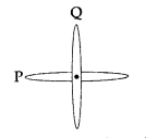
Answer: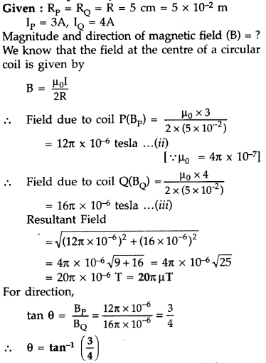
Question 89.
State the Lorentz’s force and express it in vector form.
Which pair of vectors are always perpendicular to each other? Derive the
expression for the force acting on a current carrying conductor of length L in a
uniform magnetic field ‘B’. (Comptt. Delhi 2017)
Answer:
Lorentz’s
magnetic force is force experienced by a charged particle of charge ‘q’ moving
in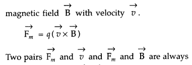
perpendicular to each other Let us consider a conductor of
uniform cross-sectional area A and length ‘U having number density of electrons
as V Total force on charge carriers in the conductor,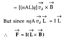
Question 90.
Define the term magnetic moment of a current loop. Derive an
expression for the magnetic field at any point along the axis of a solenoid of
length 21, and radius «, and number of terms per unit length n. (Comptt. Delhi
2017)
Answer:
(i) Definition of magnetic moment: Magnetic moment of a
current loop is equal to the product of current flowing in the loop and its
area; and its direction is along area vector as per the right handed screw
rule.
(ii) Magnetic field for solenoid :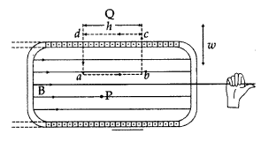
Using Ampere’s circuital law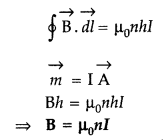
Question 91.
(a) Draw the pattern of magnetic field lines for a circular
coil carrying current.
(b) Two identical circular loops X and Y of radius R
and carrying the same current are kept in perpendicular planes such that they
have a common centre at P as shown in the figure. Find the magnitude and
direction of the net magnetic field at the point P due to the loops. (Comptt.
All India 2017)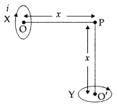
Answer:
(a) Pattern of magnetic field lines for a circular
coil carrying current :
(a) Magnetic field lines :
(b) The magnetic field due to a circular coil at a point
carrying current is given by
Since these two circular coils are identical and carrying the
same current,
Resultant magnetic field (BR)
Question 92.
Define the term current sensitivity of a galvanometer. Write
its SI unit. (Comptt. All India 2017)
Answer:
• Current sensitivity of a
galvanometer is “deflection per unit current”. It is defined as the ratio of
deflection produced in the galvanometer to the current flowing through
it.![]()
SI unit is radian per ampere.
Question 93.
A toroidal solenoid of mean radius 20 cm has 4000 turns of
wire wound on a ferromagnetic core of relative permeability 800. Calculate the
magnetic field in the core for a current of 3A , passing through the coil. How
does the field change, when this core is replaced by a core of Bismuth? (Comptt.
All India 2017)
Answer: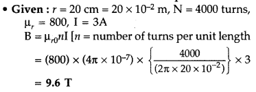
Since bismuth is diamagnetic, its μr < 1,
therefore the magnetic field in the core will be very much reduced.
Long Answer Type
Question 1.
(a) A particle of charge ‘q’ and mass ‘m’, moving with
velocity \(\vec{v}\) is subjected to a uniform magnetic field \(\vec{B}\)
perpendicular to its velocity. Show that the particle describes a circular path.
Obtain an expression for the radius of the circular path of the particle.
Answer:
Let a charged particle of charge q and mass m be moving with velocity
\(\vec{v}\) right angle to the field (i.e. in the plane of the paper), then
magnetic force \(\vec{F}\) acting on the charge q will be
\(\vec{F}=q(\vec{v}
\times \vec{B})\)
or
F = qvB sin 90°
or
F = qvB … (1)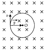
As this forces fact at a right angle to the velocity V of the charged particle,
the slot is unable to change the velocity but can make the charged particle move
In a circular path.
If r is the radius of the circle, then the centripetal force required by the
charged particle will be
\(F_{c}=\frac{m v^{2}}{r}\)
This centripetal force Is provided by the magnetic force acting on the
charged particle.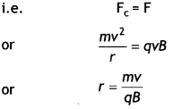
(b) Explain, how its path will be affected if the velocity \(\vec{v}\) makes an
angle (θ ≠ 90°) with the direction of the magnetic field. (CBSE 2019C)
Answer:
If (θ ≠ 90°), the velocity \(\vec{v}\) of the moving charge can be
resolved into two components v cos θ, in the direction of the magnetic field and
make it v sin θ, in the direction perpendicular to the magnetic field. The
charged particle under the combined effect of the two components of velocities
wilt cover linear as well as a circular path, i.e. helical path whose axis is
parallel to the magnetic field.
Question 2.
(a) Obtain the conditions under which an electron does not
suffer any deflection while passing through a magnetic field.
Answer:
No
deflection suffered by the electron if it moves parallel or anti-parallel to the
magnetic field.
(b) Two protons P and Q moving with the same speed pass through the magnetic
fields \(\vec{B}_{1}\) and \(\vec{B}_{2}\) respectively, at right angles to the
field directions. If \(\left|\vec{B}_{2}\right|>\left|\vec{B}_{1}\right|\),
which of the two protons will describe the circular path of smaller radius?
Explain. (CBSEAI 2019)
Answer:
The radius of the circular path traveled by
a charged particle in a magnetic field is given by
r = \(\frac{mv}{Bq}\)
Therefore, \(\frac{r_{1}}{r_{2}}=\frac{B_{2}}{B_{1}}\)
As \(\left|\vec{B}_{2}\right|>\left|\vec{B}_{1}\right|\) therefore, r2 < r1
Question 3.
A straight wire of length L is bent into a semi-circular loop.
Use Biot-Savart law to deduce an expression for the magnetic field at its center
due to the current l passing through it. (CBSE Delhi 2011C)
Answer:
Consider a straight wire of length L. Let it be bent into a semicircular arc of
radius r as shown,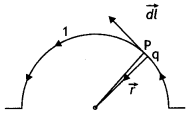
Then πr = L or r = L/π
Let a current I be passed through it. Divide the semi-circular loop into a large number of elements; consider one such element PQ of length dl. Then the small magnetic field cfB produced at the point O is
dB = \(\frac{\mu_{0}}{4 \pi} \frac{l d l \sin 90^{\circ}}{r^{2}}=\frac{\mu_{0}}{4 \pi} \frac{l d l}{r^{2}}\) outwards at point O.
Therefore total magnetic field at point O is
B = \(\int_{0}^{\pi r}
\frac{\mu_{0}}{4 \pi} \frac{l d l}{r^{2}}=\frac{\mu_{0} l}{4 r}=\frac{\mu_{0} l
\pi}{4 L}\)
Question 4.
A circular coil of N turns and radius R carries a current l.
It is unwound and rewound to make another coil of radius R/2, current l
remaining the same. Calculate the ratio of the magnetic moments of the new coil
and the original coil. (CBSE AI 2012)
Answer:
The magnetic moment of a
current-carrying coil is given by
M = n lA = n l πR²
When the coil is unwound and wound into another coil of radius R/2, the
number of turns will double, i.e. n = 2
Therefore, n1 = 1,
n2 = 2, R1 = R, R2 = R/2, hence
Therefore \(\frac{M_{2}}{M_{1}}=\frac{n_{2} / \pi R_{2}^{2}}{n_{1} / \pi R_{1}^{2}}=\frac{2}{4}=\frac{1}{2}\)
Question 5.
Two identical coils P and Q each of radius R are lying in
perpendicular planes such that they have a common center. Find the magnitude and
direction of the magnetic field at the common center when they carry currents
equal to l and \(\sqrt{3}\) l respectively. (CBSE Al 2019)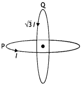
Answer:
Magnetic field at the common centre due to coil P
\(B_{1}=\frac{\mu_{o} l}{2 R}\)
Magnetic field at the common centre due to coil Q
\(B_{2}=\frac{\mu_{0}
\sqrt{3} l}{2 R}\)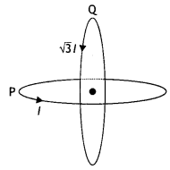
The two fields are mutually perpendicular, therefore, the resultant field at the
common centre is
B = \(\sqrt{B_{1}^{2}+B_{2}^{2}}=\sqrt{\left(\frac{\mu_{o}
l}{2 R}\right)^{2}+\left(\frac{\mu_{0} \sqrt{3} 1}{2 R}\right)^{2}}\)
=
\(\frac{\mu_{o} l}{R}\)
Let the resultant field make an angle θ with magnetic field
B<sub>2</sub> as shown
tan θ =
\(\frac{B_{1}}{B_{2}}=\frac{1}{\sqrt{3}}\) ⇒ θ = 30°
Question 6.
Find the condition under which the charged particles moving
with different speeds in the presence of electric and magnetic field vectors can
be used to select charged particles of a particular speed. (CBSE A! 2017)
Answer:
Consider crossed electric and magnetic fields. Let the particle enter
perpendicular to both these fields. Due to this, the electric and magnetic
forces are in opposite directions. Suppose, we adjust the value of E and B such
that the magnitudes of the two forces are equal. Then, the total force on the
charge is zero and the charge will move in the fields undeflected.
This happens when, or qE = qvB or v = E/B
This condition can be used to select charged particles of a particular velocity out of a beam containing charges moving at different speeds (irrespective of their charge and mass). The crossed E and B fields, therefore, serve as a velocity selector. Only particles with speed E/B pass undeflected through the region of crossed fields.
Question 7.
(a) Define the SI unit of current in terms of the force
between two parallel current-carrying conductors.
Answer:
One ampere is
that much current which when flowing through each of the two infinitely long
straight conductors held 1 meter apart in space, produces a force of F = 2 ×
10-7 N per meter of their length.
(b) Two long straight parallel conductors carrying steady currents
la and lb along the same direction are separated by a
distance d. How does one explain the force of attraction between them? If a
third conductor carrying a current l in the opposite direction is placed just in
the middle of these conductors, find the resultant force acting on the third
conductor. (CBSE AI, Delhi 2018C)
Answer:
The magnetic field produced by
one current applies a force on the other current-carrying conductor. By
Fleming’s left-hand rule the forces acting on each due to other is directed
towards each other. This shows attraction.
Force on C conductor due to conductor A
Fca = \(\frac{\mu_{0}
l_{a} l_{c}}{\pi d}\) repulsive
Force on C conductor due to conductor B
Fcb = \(\frac{\mu_{0}
l_{b} l_{c}}{\pi d}\)
Question 8.
ExplaIn how will you convert a galvanometer into a voltmeter
to read a maximum potential of ‘V’ volt. Can one use a voltmeter to measure the
emf of a cell? Justify your answer.
Answer:
Suppose a galvanometer having
resistance G is to be converted into a voltmeter, which can measure the
potential difference from O to V volt. Let a high resistance R be joined in
senes with the galvanometer for this purpose. Its value is so chosen that when
the galvanometer with the resistance is connected between two points having a
potential difference of V volt, the gaLvanometer gives full-scale deflection. It
is clear from the figure below that
V = lg (R + G)
or
R =
\(\frac{v}{l_{g}}\) – G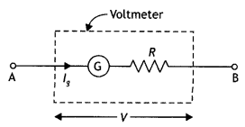
On connecting the above high resistance in series with a galvanometer, the
galvanometer is converted into a voltmeter of range V volt.
A voltmeter cannot measure the emf of the cell as it draws current from the cell while measuring the potential differences.
Question 9.
Explain how will you convert a galvanometer into an ammeter to
read a maximum current of ‘l’ ampere. An ammeter is always connected in series
with a circuit. Why? (CBSE AI 2019)
Answer:
Suppose a galvanometer of
resistance G is to be converted into an ammeter having range 0 to l ampere. Let
lg be the current,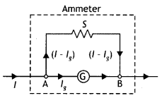
which gives full-scale deflection in the galvanometer. Suppose S is the
appropriate shunt required for this purpose, i.e. when shunt S Is used, current
‘g passes through the galvanometer and the remaining (l – lg) passes
through the shunt as shown in the figure below. Since the shunt and the
galvanometer are connected In parallel therefore the potential differences
across both wilL be the same. Hence
lg G = (l – lg) S
….(1)
S = \(\frac{l_{s} G}{l-l_{s}}\) ….(2)
An ammeter is used to measure current; therefore, it is connected in senes so that the entire current passes through it. Moreover, an ammeter is a low resistance device.
Question 10.
A steady current (l1) flows through a long
straight wire. Another wlrè carrying steady current (l2) In the same
direction is kept close and parallel to the first wire. Show with the help of a
diagram how the magnetic field due to the current l1 exerts a
magnetic force on the second wire. Write the expression for this force. (CBSE AI
2011)
Answer:
The diagram is as shown below.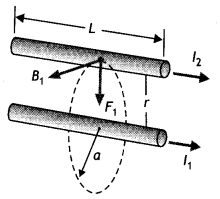
Magnetic field B1 is produced by the wire carrying current l1 on a
wire carrying current l2. Thus the second current-carrying wire is
placed in the magnetic field produced by the first as a result it experiences a
force is given by F = \(\frac{\mu_{0} l_{1} l_{2}}{2 \pi r}\) per unit
length.
Question 11.
(a) Using Biot-Savart’s law, derive an expression for the
magnetic field at the centre of a circular coil of radius R, number of turns N,
carrying current i.
(b) Two small identical circular coils marked 1, 2 carry
equal currents and are placed with their geometric axes perpendicular to each
other as shown in the figure. Derive an expression for the resultant magnetic
field at O. (Delhi 2017)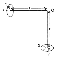
Answer:
(a) Consider a circular loop of wire of radius R
carrying current I. The entire loop can be divided into a large number of small
current elements.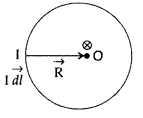
According to Biot-Savart’s law, magnetic field due to current
element ‘Idl’ at the centre O of a coil is
The direction of d \(\vec{l}\) is along the tangent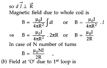
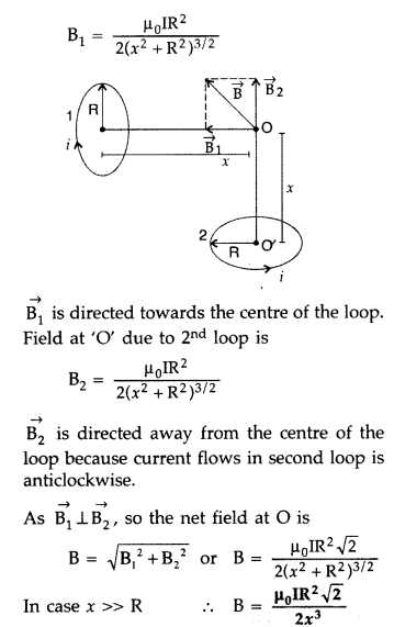
Question 12.
Draw a schematic diagram of a cyclotron. Explain its
underlying principle and working, stating clearly the function of the electric
and magnetic field applied on a charged particle. Deduce an expression for the
period of revolution and show that it does not depend on the speed of the
charged particle. (Delhi 2017)
Answer:
Principle : When a positively
charged particle is made to move again and again in a high frequency electric
field, it gets accelerated and acquires sufficiently large amount of
energy.
Working : Suppose a positive ion, say a proton, enters the
gap between the two dees and finds dee D1 to be negative. It gets
accelerated towards dee D1. As it enters the dee D1, it
does not experience any electric field due to shielding
effect of the
metallic dee. The perpendicular magnetic field throws it into a circular
path.
At the instant the proton comes out of dee D1. It finds dee
D1 positive and dee D2 negative. It now gets accelerated
towards dee D2. It moves faster through dee D2 describing
a larger semicircle than before. Thus if the frequency of the applied voltage is
kept exactly the same as the frequency of the revolution of the proton, then
everytime the proton reaches the gap between the two dees, the electric field is
reversed and proton receives a push and finally it acquires very high energy.
This proton follows a spiral path. The accelerated proton is ejected through a
window by a deflecting voltage and hits the target.
Centripetal force is
provided by magnetic field to charged particle to move in a circular
back.
Question 13.
Draw a schematic sketch of a cyclotron. Explain briefly how
it works and how it is used to accelerate the charged particles.
(i) Show
that time period of ions in a cyclotron is independent of both the speed and
radius of circular path.
(ii) What is resonance condition? How is it used to
accelerate the charged particles? (All India 2017)
Answer:
(i) Principle :
When a positively charged particle is made to move again and again in a high
frequency electric field, it gets accelerated and acquires sufficiently large
amount of energy.
Working : Suppose a positive ion, say a proton, enters the
gap between the two dees and finds dee D1 to be negative. It gets
accelerated towards dee D1. As it enters the dee D1, it
does not experience any electric field due to shielding effect of the metallic
dee. The perpendicular magnetic field throws it into a circular path.
At the instant the proton comes out of dee D1. It finds dee
D1 positive and dee D2 negative. It now gets accelerated
towards dee D2. It moves faster through dee D2 describing
a larger semicircle than before. Thus if the frequency of the applied voltage is
kept exactly the same as the frequency of the revolution of the proton, then
everytime the proton reaches the gap between the two dees, the electric field is
reversed and proton receives a push and finally it acquires very high energy.
This proton follows a spiral path. The accelerated proton is ejected through a
window by a deflecting voltage and hits the target.
Centripetal force is
provided by magnetic field to charged particle to move in a circular
back.
(ii) The frequency va of the applied voltage is
adjusted so that the polarity of the dees is reversed in the same time that it
takes the ions to complete one-half of the revolution. The requirement
va = vc is called the resonance condition.
The phase of
the supply is adjusted so that when the positive ions arrive at the edge of
D1, D2 is at a lower potential and the ions are
accelerated across the gap.
Question 14.
(a) Two straight long parallel conductors carry currents
I1 and I2 in the same direction. Deduce the expression for
the force per unit length between them.
Depict the pattern of magnetic field
lines around them.
(b) A rectangular current carrying loop EFGH is kept in a
uniform magnetic field as shown in the figure.
(i) What is the direction of
the magnetic moment of the current loop?
(ii) When is the torque acting on
the loop
(A) maximum,
(B) zero? (All India 2017)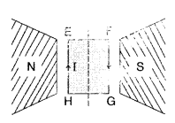
Answer:
Consider two infinitely long parallel conductors
carrying current I1 and I2 in the same direction.
Let d
be the distance of separation between these two conductors.
Hence, force is attractive in nature.
Ampere : Ampere is
that current which is if maintained in two infinitely long parallel conductors
of negligible cross-sectional area separated by 1 metre in vacuum causes a force
of 2 × 10⁻⁷ N on each metre of the other wire.
Then current
flowing is 1A

(i) Magnetic moment will be out of the plane from the surface
HEFG.
(ii) Torque
(A) Torque is maximum when MII B i.e., when it gets
rotated by 90°.
(B) Torque is minimum when M and B are at 270° to each
other.
Question 15.
(a) With the help of a diagram, explain the principle and
working of a moving coil galvanometer.
(b) What is the importance of a radial
magnetic field and how is it produced?
(c) Why is it that while using a
moving coil galvanometer as a voltmeter a high resistance in series is required
whereas in an ammeter a shunt is used? (All India)
Answer:
(a) Principle :
“If a current carrying coil is freely suspended/pivoted in a uniform magnetic
field, it experiences a deflecting torque.”
Working: As the pivoted coil is
placed in a radial magnetic field, hence on passing current I through it, a
deflecting torque acts on the coil which is given by, τ = NAIB![]()
The spring Sp attached to the coil provides the
counter torque and in equilibrium state balances the deflecting torque. If φ is
steady angular deflection then counter torque is kφ.
…where [k = torsional
constant of the spring
In equilibrium state,![]()
Thus, deflection is directly proportional to the current
flowing in the coil.
(a) (i) Uniform radial magnetic field. It keeps the
magnetic field line normal to the area vector of the coil.
(ii) Soft iron
core in galvanometer. The cylindrical soft iron core, when placed inside the
coil of a galvanometer, makes the magnetic field stronger and radial in the
space between it and pole pieces, such that whatever the position of the
rotation of the coil may be, the magnetic field is always parallel to its
plane.
(b) (i) Current sensitivity is defined as the deflection produced in the
galvanometer when unit current is passed through its coil.
(ii) Voltage sensitivity is defined as the deflection
produced in the galvanometer when unit voltage is applied across the coil of the
galvanometer.
…where [R = Resistance of the coil![]()
does not necessarily increase the voltage sensitivity. It may
be affected by the resistance used.
(b) For radial magnetic field, sin θ = 1,
so torque τ = NIAB.
Thus when
radial magnetic field is used, the deflection of the coil is proportional to the
current flowing through it. Hence a linear scale can be used to determine the
deflection of the coil.
(c) A high resistance is joined in series with a galvanometer so that when the arrangement (voltmeter) is used in parallel with the selected section of the circuit, it should draw least amount of current. In case voltmeter draws appreciable amount of current, it will disturb the original value of potential difference by a good amount.
To convert a galvanometer into ammeter, a shunt is used in parallel with it so that when the arrangement is joined in series, the maximum current flows through the shunt, and thus the galvanometer is saved from its damage, when the current is passed through ammeter.
Question 16.
(a) Derive an expression for the force between two long
parallel current carrying conductors.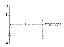
(b) Use this expression to define S.I. unit of current.
(c) A long straight wire AB carries a current I. A proton P travels with a speed
v, parallel to the wire, at a distance d from it in a direction opposite to the
current as shown in the figure. What is the force experienced by the proton and
what is its direction? (All India)
Answer:
(a) For (a) and (b) :
Consider two infinitely long parallel conductors carrying current I1
and I2 in the same direction.
Let d be the distance of separation
between these two conductors.
Hence, force is attractive in nature.
Ampere : Ampere is
that current which is if maintained in two infinitely long parallel conductors
of negligible cross-sectional area separated by 1 metre in vacuum causes a force
of 2 × 10⁻⁷ N on each metre of the other wire.
Then current
flowing is 1A

(c) Force experienced by the proton,![]()
As magnetic field due to the current carrying wire is
directed into the plane of the paper (θ = 90°)![]()
Force is directed away from the current carrying wire or in
the right direction of observer.
Question 17.
State Biot-Savart law, giving the mathematical expression for
it.
Use this law to derive the expression for the magnetic field due to a
circular coil carrying current at a point along its axis.
How does a circular
loop carrying current behave as a magnet? (Delhi 2011)
Answer:
According
to Biot-Savart’s law, “magnetic field acting at a particular point due to
current carrying element is proportional to the division of cross product of
current element and position vector of point where the field is to be calculated
from the current element to the cube of the distance between current element and
the point where the field is to be calculated”.

Magnetic field on the axis of circular current loop :
As in a special case we may obtain the field at the centre of
the loop. Here x = 0, and we obtain![]()
In a current loop, both the opposite faces behave as opposite
poles, making it a magnetic dipole. One side of the current carrying coil
behaves like the N-pole and the other side as the S-pole of a magnet.
Question 18.
With the help of a labelled diagram, state the underlying
principle of a cyclotron. Explain clearly how it works to accelerate the charged
particles. Show that cyclotron frequency is independent of energy of the
particle. Is there an upper limit on the energy acquired by the particle? Give
reason. (Delhi 2011)
Answer:
Principle : When a positively charged
particle is made to move again and again in a high frequency electric field, it
gets accelerated and acquires sufficiently large amount of energy.
Working : Suppose a positive ion, say a proton, enters the
gap between the two dees and finds dee D1 to be negative. It gets
accelerated towards dee D1. As it enters the dee D1, it
does not experience any electric field due to shielding effect of the metallic
dee. The perpendicular magnetic field throws it into a circular path.
At the instant the proton comes out of dee D1. It finds dee
D1 positive and dee D2 negative. It now gets accelerated
towards dee D2. It moves faster through dee D2 describing
a larger semicircle than before. Thus if the frequency of the applied voltage is
kept exactly the same as the frequency of the revolution of the proton, then
everytime the proton reaches the gap between the two dees, the electric field is
reversed and proton receives a push and finally it acquires very high energy.
This proton follows a spiral path. The accelerated proton is ejected through a
window by a deflecting voltage and hits the target.
Centripetal force is
provided by magnetic field to charged particle to move in a circular
back.
Yes, there is an upper limit. The increase in the kinetic energy of particles is qv. Therefore, the radius of their path goes on increasing each time, their kinetic energy increases. The lines are repeatedly accelerated across the dees, untill they have the required energy to have a radius approximately that of the dees. Hence, this is the upper limit on the energy required by the particles due to definite size of dees.
Question 19.
(a) State the principle of the working of a moving coil
galvanometer, giving its labelled diagram.
(b) “Increasing the current
sensitivity of a galvanometer may not necessarily increase its voltage
sensitivity.” Justify this statement
(c) Outline the necessary steps to
convert a galvanometer of resistance RG into an ammeter of a given range. (All
India 2011)
Answer:
(a)
Principle : “If a current carrying coil is
freely suspended/pivoted in a uniform magnetic field, it experiences a
deflecting torque.”
Working: As the pivoted coil is placed in a radial
magnetic field, hence on passing current I through it, a deflecting torque acts
on the coil which is given by, τ = NAIB![]()
The spring Sp attached to the coil provides the
counter torque and in equilibrium state balances the deflecting torque. If φ is
steady angular deflection then counter torque is kφ.
…where [k = torsional
constant of the spring
In equilibrium state,![]()
Thus, deflection is directly proportional to the current
flowing in the coil.
(a) (i) Uniform radial magnetic field. It keeps the
magnetic field line normal to the area vector of the coil.
(ii) Soft iron
core in galvanometer. The cylindrical soft iron core, when placed inside the
coil of a galvanometer, makes the magnetic field stronger and radial in the
space between it and pole pieces, such that whatever the position of the
rotation of the coil may be, the magnetic field is always parallel to its
plane.
(b) (i) Current sensitivity is defined as the deflection produced in
the galvanometer when unit current is passed through its coil.
(ii) Voltage sensitivity is defined as the deflection
produced in the galvanometer when unit voltage is applied across the coil of the
galvanometer.
…where [R = Resistance of the coil![]()
does not necessarily increase the voltage sensitivity. It may
be affected by the resistance used.
(b) Since \(\mathrm{v}_{\mathrm{s}}=\frac{\mathrm{I}_{\mathrm{s}}}{\mathrm{R}}\) increase in current sensitivity may not necessarily increase the voltage sensitivity. It may be affected by the resistance used.
(c) Conversion of galvanometer into ammeter: By just connecting a low
resistance known as shunt in parallel to the galvanometer, it can be converted
into an ammeter.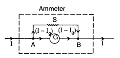
Let G = resistance of the galvanometer.
Ig =
the current with which galvanometer gives full scale deflection.
S = shunt
resistance
I – Ig = current through the shunt.
As the
galvanometer and shunt are connected in parallel,
Potential difference across
the galvanometer = Potential difference across the shunt
Question 20.
(a) Write the expression for the force,
\(\overrightarrow{\mathbf{F}}\), acting on a charged particle of charge ‘q’,
moving with a velocity latex]\overrightarrow{\mathbf{v}}[/latex] in the presence
of both electric field \(\overrightarrow{\mathrm{E}}\) and magnetic field
\(\overrightarrow{\mathrm{B}}\). Obtain the condition under which the particle
moves undeflected through the fields.
(b) A rectangular loop of size l × b
carrying a steady current I is placed in a uniform magnetic field
\(\overrightarrow{\mathrm{B}}\). Prove that the torque \(\vec{\tau}\) acting on
the loop is given by \(\vec{\tau}=\vec{m} \times \overrightarrow{\mathrm{B}}\),
where \(\overrightarrow{\mathrm{m}}\) is the magnetic moment of the loop. (All
India 2011)
Answer:
(a) A charge q in an electric field
\(\overrightarrow{\mathrm{E}}\) experiences the electric force,
\(\overrightarrow{\mathrm{F}}_{e}=q \overrightarrow{\mathrm{E}}\)
This force acts in the direction of field \(\overrightarrow{\mathrm{E}}\) and is independent of the velocity of the charge.
The magnetic force experienced by the charge q moving with velocity
\(\overrightarrow{\mathrm{v}}\) in the magnetic field B is given by![]()
This force acts perpendicular to the plane of
\(\overrightarrow{\mathrm{V}}\) and \(\overrightarrow{\mathrm{B}}\) and depends
on the velocity \(\overrightarrow{\mathrm{v}}\) of the charge.
The total force, or the Lorentz force, experienced by the charge q due to
both electric and magnetic field is given by
Hence, A stationary charged particle does not experience any
force in a magnetic field. (b) Torque on a current loop in a uniform magnetic
field.
Let I = Current flowing through the coil PQRS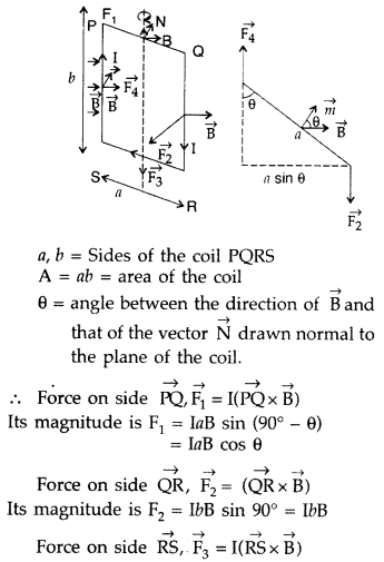
Its magnitude is, F3 = IaB sin(90° + 0)
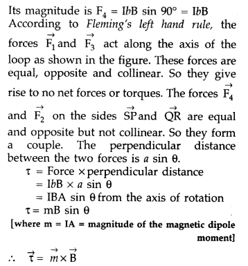
Question 21.
(a) Explain, giving reasons, the basic difference in
converting a galvanometer into
(i) a voltmeter and
(ii) an ammeter.
(b)
Two long straight parallel conductors carrying steady currents I1 and
I2 are separated by a distance’d’ Explain briefly, with the help of a
suitable diagram, how the magnetic field due to one conductor acts on the other.
Hence deduce the expression for the force acting between the two conductors.
Mention the nature of this force.
Answer:
(a) (i) Voltmeter is connected
in parallel with the circuit element across which the potential difference is
intended to be measured.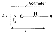
A galvanometer can be converted into a voltmeter by
connecting a higher resistance in series with it. The value of this resistance
is so adjusted that only current I which produces full scale deflection in the
galvanometer, passes through the galvanometer.
(ii) A galvanometer can be converted into an ammeter by
connecting a low value
resistance in parallel with it.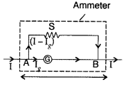

(b)
Consider two infinitely long parallel conductors
carrying current I1 and I2 in the same direction.
Let d
be the distance of separation between these two conductors.
Hence, force is attractive in nature.
Ampere : Ampere is
that current which is if maintained in two infinitely long parallel conductors
of negligible cross-sectional area separated by 1 metre in vacuum causes a force
of 2 × 10⁻⁷ N on each metre of the other wire.
Then current
flowing is 1A

Question 22.
(a) Explain briefly with the help of a labelled diagram, the
principle and working of a moving coil galvanometer.
(b) Define the term
‘current sensitivity’ of a galvanometer. How is it that increasing current
sensitivity may not necessarily increase its voltage sensitivity? Explain.
(Comptt. All India 2011)
Answer:
(a) Principle and working of a moving
coil galvanometer:
Principle : “If a current carrying coil is freely
suspended/pivoted in a uniform magnetic field, it experiences a deflecting
torque.”
Working: As the pivoted coil is placed in a radial magnetic field,
hence on passing current I through it, a deflecting torque acts on the coil
which is given by, τ = NAIB![]()
The spring Sp attached to the coil provides the
counter torque and in equilibrium state balances the deflecting torque. If φ is
steady angular deflection then counter torque is kφ.
…where [k = torsional
constant of the spring
In equilibrium state,![]()
Thus, deflection is directly proportional to the current
flowing in the coil.
(a) (i) Uniform radial magnetic field. It keeps the
magnetic field line normal to the area vector of the coil.
(ii) Soft iron
core in galvanometer. The cylindrical soft iron core, when placed inside the
coil of a galvanometer, makes the magnetic field stronger and radial in the
space between it and pole pieces, such that whatever the position of the
rotation of the coil may be, the magnetic field is always parallel to its
plane.
(b) (i) Current sensitivity is defined as the deflection produced in
the galvanometer when unit current is passed through its coil.
(ii) Voltage sensitivity is defined as the deflection
produced in the galvanometer when unit voltage is applied across the coil of the
galvanometer.
…where [R = Resistance of the coil![]()
does not necessarily increase the voltage sensitivity. It may
be affected by the resistance used.
(b) Current sensitivity:
(a)
Principle : “If a current carrying coil is freely suspended/pivoted in
a uniform magnetic field, it experiences a deflecting torque.”
Working: As
the pivoted coil is placed in a radial magnetic field, hence on passing current
I through it, a deflecting torque acts on the coil which is given by, τ =
NAIB![]()
The spring Sp attached to the coil provides the
counter torque and in equilibrium state balances the deflecting torque. If φ is
steady angular deflection then counter torque is kφ.
…where [k = torsional
constant of the spring
In equilibrium state,![]()
Thus, deflection is directly proportional to the current
flowing in the coil.
(a) (i) Uniform radial magnetic field. It keeps the
magnetic field line normal to the area vector of the coil.
(ii) Soft iron
core in galvanometer. The cylindrical soft iron core, when placed inside the
coil of a galvanometer, makes the magnetic field stronger and radial in the
space between it and pole pieces, such that whatever the position of the
rotation of the coil may be, the magnetic field is always parallel to its
plane.
(b) (i) Current sensitivity is defined as the deflection produced in
the galvanometer when unit current is passed through its coil.
(ii) Voltage sensitivity is defined as the deflection
produced in the galvanometer when unit voltage is applied across the coil of the
galvanometer.
…where [R = Resistance of the coil![]()
does not necessarily increase the voltage sensitivity. It may
be affected by the resistance used.
(b) Current sensitivity is defined as the deflection produced in the
galvanometer when unit current is passed through its coil.
may not necessarily increase the voltage sensitivity. It may
be affected by the resistance used.
Question 23.
(a) State Biot-Savart law. Deduce the expression for the
magnetic field due to a circular current carrying loop at a point lying on its
axis.
(b) Two long parallel wires carry currents I1 and
I2 flowing in the same direction. When a third current carrying wire
is placed parallel and coplanar in between the two, find the condition when the
third wire would experience no force due to these two wires. (Comptt. All India
2011)
Answer: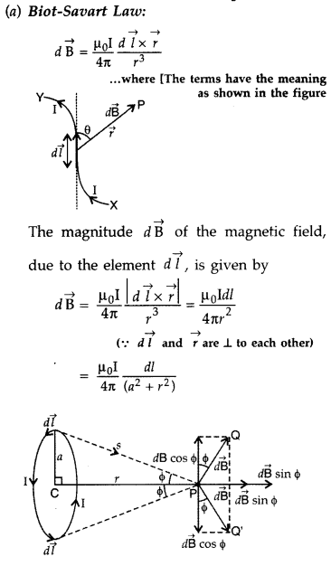
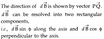
The components perpendicular to the axis of the loop will be
equal and opposite to component along the axis of the loop and will cancel out.
Their axial components will be in the same direction, i.e., along CP and get
added up.
∴ Total magnetic field at point P in the direction CP is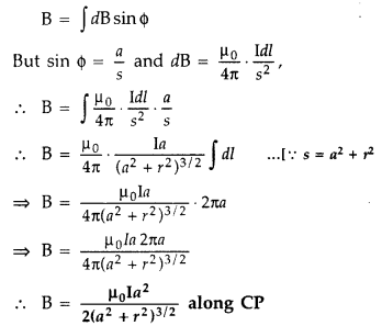
The direction of this field is along the axis, in the sense
given by the right hand (thumb) rule.
(b) The force
\(\overrightarrow{f_{1}}\) on the third wire due to wire 1 is directed opposite
to the force \(\overrightarrow{f_{2}}\) on the third wire due to wire 2. Hence,
the net force on the third wire would become 0.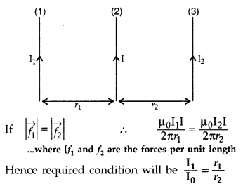
Question 24.
(a) Derive the expression for the torque on a rectangular
current carrying loop suspended in a uniform magnetic field.
(b) A proton and
a deutron having equal momenta enter in a region of uniform magnetic field at
right angle to the direction of the field. Depict their trajectories in the
field. (Delhi 2013)
Answer:
(a) Torque on a rectangular current loop in a
uniform magnetic field:
Let I = current through the coil
a, b – sides of
the rectangular loop
A = ab = area of the loop
n = Number of turns in the
loop
B = Magnetic field
θ = angle between magnetic field
\(\overrightarrow{\mathrm{B}}\) and area vector
\(\overrightarrow{\mathrm{A}}\)
Force exerted on the arm DA inward
F1 = I b B
…[∵ F = ILB]
Force exerted on the arm BC outward
F2 = I b B ∴
F2 = F1
Thus net force on the loop is zero
∴ Two
equal and opposite forces form a couple which exerts a torque
∴ Magnitude of
the torque on the loop is,
If loop has n turns then M = n I A
∴ τ = nIAB sin
θ
When θ = 90° then \(\tau_{\max }=n I A B\)
When θ = 0° then τ = 0
(b)
Since the momentum and the charge on both the proton and deutron are the same,
the particle will follow a circular path with radius 1:1.
Question 25.
(a) Using Biot-Savart’s law, derive the expression for the
magnetic field in the vector form at a point on the axis of a circular current
loop.
(b) What does a toroid consist of? Find out the expression for the
magnetic field inside a toroid for N turns of the coil having the average radius
r and carrying a current I. Show that the magnetic field in the open space
inside and exterior to the toroid is zero. (All India 2013)
Answer:
(a)
Let P be the point on the axis of a circular loop or coil of radius a carrying
current I. The distance of P from the centre of loop is x.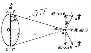
According to Biot-Savart’s Law, magnetic field due to a small
element XY (dl) at point P is![]()
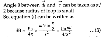
The perpendicular components of the magnetic field due to
these elements being equal and opposite cancel each other. Hence the total
contribution of perpendicular components, (i.e. dB cos θ) to the net magnetic
field is zero.
On the other hand, dB sin θ component of magnetic field due to each element of the coil or loop is directed in the same direction.
Therefore, magnetic field at point P due to the whole coil or loop is equal
to the sum of dB sin θ components of magnetic field due to each element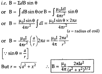
The right hand thumb rule can be used to find the direction
of the field.
(b) A toroid is a solenoid bent to form a ring shape.
Let N
number of turns per unit length of toroid and I be current flowing in
it.
Consider a loop (region II) of radius r passes through the
centre of the toroid.
Let (region II) \(\overrightarrow{\mathrm{B}}\) be
magnetic field along the loop is
Let (region I) B1 be magnetic field outside toroid
in open space. Draw an amperian loop L2 of radius r2
through point Q.
Now applying ampere’s law :
As I = 0, because the circular turn current coming out of
plane of paper is cancelled exactly by current going into it, so net I = 0,
equation (i) becomes
Question 26.
(a) Draw a schematic sketch of a cyclotron. Explain clearly
the role of crossed electric and magnetic field in accelerating the charge.
Hence derive the expression for the kinetic energy acquired by the
particles.
(b) An α-particle and a proton are realeased from the centre of
the cyclotron and made to accelerate.
(i) Can both be accelerated at the same
cyclotron frequency? Give reason to justify your answer.
(ii) When they are
accelerated in turn, which of the two will have higher velocity at the exit slit
of the dees? (All India 2013)
Answer:
(a) Cyclotron :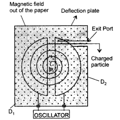
Role of crossed electric and magnetic field in cyclotron :
The magnetic field makes the charged particle to cross the gap between the dees
again and again by making it move along a circular path, while the oscillating
electric field, applied across the dees, accelerates the charged particle again
and again and hence increases its K.E.
Expression :
If the velocity v is
perpendicular to the magnetic field B, the magnetic force is perpendicular to
both v and B and acts like a centripetal force. It has a magnitude qvB. Equating
the two expressions for centripetal force,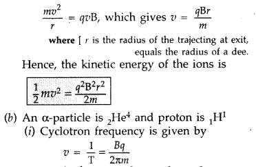
No, both cannot be accelerated to same frequency because
frequency depends upon mass and charge.
(ii) Velocity is given by the formula
v = \(\frac{B q r}{m}\)
Velocity is also inversely proportional to mass and
directly proportional to charge
Velocity of proton is higher than that α-particle.
Question 27.
State Biot-Savart law, expressing it in the vector form. Use
it to obtain the expression for the magnetic field at an axial point, distance
‘d’ from the centre of a circular coil of radius V carrying current T. Also find
the ratio of the magnitudes of the magnetic field of this coil at the centre and
at an axial point for which
d = a√3. (Comptt. Delhi 2013)
Answer:
(a)
Biot-Savart law : It states that “the magnetic field dB due to a current element
d l at any point P is:
(i) directly proportional to current dB ∝ I.
(ii)
directly proportional to the length dl of the element \(d \vec{B}\) ∝ dl.
(iii) directly proportional to sin θ, where θ is the angle between
d\(\overrightarrow{l}\) and \(\overrightarrow{r}\),
Therefore \(d \vec{B}\) ∝
sin θ
(iv) inversely proportional to the square of the distance r from the
current element![]()

Combining (i), (ii), (iii) and (iv), we get
The direction of \(\overrightarrow{d \mathrm{B}}\) is
perpendicular to the plane of the vector d \(\vec{l}\) and \(\vec{r}\) given by
Right Handed Screw Rule.
(b) Consider a circular coil of radis r, carrying
current I. It consists of a large number of small current elements of length dl.
According to Biot-Savart law, magnetic field at the centre O due to current
element dl is,
Magnetic field due to all such current elements will point
into the plane of paper.
Hence total field at O is,

Question 28.
(a) Draw the magnetic field lines due to a
current carrying loop.
(b) State using a suitable diagram, the working
principle of a moving coil galvanometer. What is the function of a radial
magnetic field and the soft iron core used in it?
(c) For converting a
galvanometer into an ammeter, a shunt resistance of small value is used in
parallel, whereas in the case of a voltmeter a resistance of large value is used
in series. Explain why. (Comptt. Delhi 2011)
Answer:
(a) Magnetic field
lines :
(b) Moving coil galvanometer. It is a device used for the
detection and measurement of small electric current.
Principle. The working
is based on the fact that a current carrying coil suspended in a magnetic field
experiences a torque.
Construction. It consists of a coil having a large
number of turns of insulated copper wire wound on a metallic frame. The coil is
suspended by means of a phosphor-bronze strip and is surrounded by a horse-shoe
magnet NS. A hair spring is attached to lower end of the coil. The other end of
the spring is attached to the scale through a pointer.
Working. When current is passed, say along ABCD, the couple acts on it. Since the plane remains always parallel to the magnetic field in all positions of the coil (radial field), the force on the vertical arms always remains perpendicular to the place of the coil.
Let, I be the current flowing through coil,
B be magnetic field supposed
to be uniform and always parallel to the coil, A be area of the coil
Deflecting torque acting on the coil is,
τ = nI BA sin 900
Due to deflecting torque, the coil rotates and suspension wire gets twisted.
A restoring torque is set up in the suspension fibre. If <|) is angle through
which the coil rotates and k is the restoring torque per unit angular twist,
then restoring torque, τ = kϕ
In equilibrium,
Deflecting torque =
Restoring torque
This provide a linear scale for the galvanometer.
Function
of a radial magnetic field : Radial magnetic field being normal in all
directions is formed to get maximum torque.
Function of Soft iron core, which
not only makes the field radial but also increases the strength of the magnetic
field.
(c) One uses a shunt resistance in parallel with the galvanometer, so
that most of the current passes through the shunt. In the case of a voltmeter, a
resistance of large value is used in series because it must draw a very small
current, otherwise the voltage measurement will disturb the original set up by
an amount which is very large.
Question 29.
(a) Deduce an expression for the frequency of revolution of
a charged particle in a magnetic field and show that it is independent of
velocity or energy of the particle.
(b) Draw a schematic sketch of a
cyclotron. Explain, giving the essential details of its construction, how it is
used to accelerate the charged particles. (All India 2011)
Answer:
(a)
When a charged particle with charge q moves inside a magnetic field
\(\overrightarrow{\mathrm{B}}\) with velocity v, it experiences a force, which
is given by
Here, \(\overrightarrow{\mathrm{v}}\) is perpendicular to
\(\overrightarrow{\mathrm{B}}\), \(\overrightarrow{\mathrm{F}}\) is the force on
the charged particle which acts as the centripetal force and makes it move along
a circular path.
Let m be the mass of the charged particle and r be the radius
of the circular path.
Time period of circular motion of the charged particle
can be calculated as shown below:
Therefore, the frequency of the revolution of the charged
particle is independent of the velocity or the energy of tire particle.
(b)
Cyclotron.
Principle : When a positively charged particle is made to move
again and again in a high frequency electric field, it gets accelerated and
acquires sufficiently large amount of energy.
Working : Suppose a positive ion, say a proton, enters the
gap between the two dees and finds dee D1 to be negative. It gets
accelerated towards dee D1. As it enters the dee D1, it
does not experience any electric field due to shielding effect of the metallic
dee. The perpendicular magnetic field throws it into a circular path.
At the instant the proton comes out of dee D1. It finds dee
D1 positive and dee D2 negative. It now gets accelerated
towards dee D2. It moves faster through dee D2 describing
a larger semicircle than before. Thus if the frequency of the applied voltage is
kept exactly the same as the frequency of the revolution of the proton, then
everytime the proton reaches the gap between the two dees, the electric field is
reversed and proton receives a push and finally it acquires very high energy.
This proton follows a spiral path. The accelerated proton is ejected through a
window by a deflecting voltage and hits the target.
Centripetal force is
provided by magnetic field to charged particle to move in a circular
back.
Question 30.
(a) Draw a labelled diagram of a moving coil galvanometer.
Describe briefly its principle and working.
(b) Answer the following :
(i)
Why is it necessary to introduce a cylindrical soft iron core inside the coil of
a galvanometer?
(ii) Increasing the current sensitivity of a galvanometer may
not necessarily increase its voltage sensitivity. Explain, giving reason. (All
India 2011)
Answer:
(a) Moving coil galvanometer.
Principle : “If a
current carrying coil is freely suspended/pivoted in a uniform magnetic field,
it experiences a deflecting torque.”
Working: As the pivoted coil is placed
in a radial magnetic field, hence on passing current I through it, a deflecting
torque acts on the coil which is given by, τ = NAIB![]()
The spring Sp attached to the coil provides the
counter torque and in equilibrium state balances the deflecting torque. If φ is
steady angular deflection then counter torque is kφ.
…where [k = torsional
constant of the spring
In equilibrium state,![]()
Thus, deflection is directly proportional to the current
flowing in the coil.
(a) (i) Uniform radial magnetic field. It keeps the
magnetic field line normal to the area vector of the coil.
(ii) Soft iron
core in galvanometer. The cylindrical soft iron core, when placed inside the
coil of a galvanometer, makes the magnetic field stronger and radial in the
space between it and pole pieces, such that whatever the position of the
rotation of the coil may be, the magnetic field is always parallel to its
plane.
(b) (i) Current sensitivity is defined as the deflection produced in
the galvanometer when unit current is passed through its coil.
(ii) Voltage sensitivity is defined as the deflection
produced in the galvanometer when unit voltage is applied across the coil of the
galvanometer.
…where [R = Resistance of the coil![]()
does not necessarily increase the voltage sensitivity. It may
be affected by the resistance used.
(b) (i) Iron core in galvanometer. The
cylindrical soft iron core, when placed inside the coil of a galvanometer, makes
the magnetic field stronger and radial in the space between it and pole pieces,
such that whatever the position of the rotation of the coil may be, the magnetic
field is always parallel to its plane.
(ii) Current sensitivity and voltage
sensitivity.
(a)
Principle : “If a current carrying coil is freely suspended/pivoted in
a uniform magnetic field, it experiences a deflecting torque.”
Working: As
the pivoted coil is placed in a radial magnetic field, hence on passing current
I through it, a deflecting torque acts on the coil which is given by, τ =
NAIB![]()
The spring Sp attached to the coil provides the
counter torque and in equilibrium state balances the deflecting torque. If φ is
steady angular deflection then counter torque is kφ.
…where [k = torsional
constant of the spring
In equilibrium state,![]()
Thus, deflection is directly proportional to the current
flowing in the coil.
(a) (i) Uniform radial magnetic field. It keeps the
magnetic field line normal to the area vector of the coil.
(ii) Soft iron
core in galvanometer. The cylindrical soft iron core, when placed inside the
coil of a galvanometer, makes the magnetic field stronger and radial in the
space between it and pole pieces, such that whatever the position of the
rotation of the coil may be, the magnetic field is always parallel to its
plane.
(b) (i) Current sensitivity is defined as the deflection produced in
the galvanometer when unit current is passed through its coil.
(ii) Voltage sensitivity is defined as the deflection
produced in the galvanometer when unit voltage is applied across the coil of the
galvanometer.
…where [R = Resistance of the coil![]()
does not necessarily increase the voltage sensitivity. It may
be affected by the resistance used.
(b) Current sensitivity is defined as the deflection produced in the
galvanometer when unit current is passed through its coil.
may not necessarily increase the voltage sensitivity. It may
be affected by the resistance used.
Question 31.
(a) State Ampere’s circuital law. Use this law to obtain the
expression for the magnetic field inside an air cored toroid of average radius
r, having ‘n’ turns per unit length and carrying a steady current I.
(b) 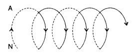
An observer to the left of a solenoid of N turns each of
cross section area ‘A’ observes that a steady current I in it flows in the
clockwise direction. Depict the magnetic field lines due to the solenoid
specifying its polarity and show that it acts as a bar magnet of magnetic moment
m = NIA. (Delhi 2011)
Answer:
(a) (i) Ampere’s Circuital Law. Line
integral of magnetic field over a closed loop is equal to |i0 times the total
current passing through the surface enclosed by the loop. Alternatively![]()
(ii) Expression for magnetic field inside toroid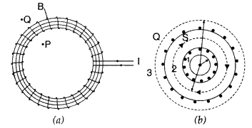
Let the current flowing through each turn of the toroid be I.
The total number of turns equals n(2nr) where n is the number of turns per unit
length. Applying Ampere’s circuital law, for the Amperian loop, for interior
points.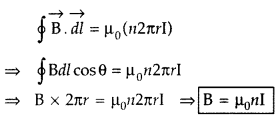
This is the expression for magnetic field inside air-cored
toroid.
(b)
(i)Depiction of magnetic field for a solenoid.
(ii) The solenoid contains N loops, each carrying a current
I. Therefore, each loop acts as a magnetic dipole. The magnetic moment for a
current I, flowing in loop of area (vector) A is given by, m = IA. The magnetic
moments of all loops are aligned along the same direction.
Hence, net
magnetic moment equals NIA.
Question 32.
Explain, using a labelled diagram, the principle and working
of a moving coil galvanometer.
(a) What is the function of
(i) uniform
radial magnetic field,
(ii) soft iron core?
(b)Define the terms
(i)
current sensitivity and
(ii) voltage sensitivity of a galvanometer. Why does
increasing the current sensitivity not necessarily increase voltage sensitivity?
(All India 2011)
Answer:
Principle : “If a current carrying coil is freely
suspended/pivoted in a uniform magnetic field, it experiences a deflecting
torque.”
Working: As the pivoted coil is placed in a radial magnetic field,
hence on passing current I through it, a deflecting torque acts on the coil
which is given by, τ = NAIB![]()
The spring Sp attached to the coil provides the
counter torque and in equilibrium state balances the deflecting torque. If φ is
steady angular deflection then counter torque is kφ.
…where [k = torsional
constant of the spring
In equilibrium state,![]()
Thus, deflection is directly proportional to the current
flowing in the coil.
(a) (i) Uniform radial magnetic field. It keeps the
magnetic field line normal to the area vector of the coil.
(ii) Soft iron
core in galvanometer. The cylindrical soft iron core, when placed inside the
coil of a galvanometer, makes the magnetic field stronger and radial in the
space between it and pole pieces, such that whatever the position of the
rotation of the coil may be, the magnetic field is always parallel to its
plane.
(b) (i) Current sensitivity is defined as the deflection produced in
the galvanometer when unit current is passed through its coil.
(ii) Voltage sensitivity is defined as the deflection
produced in the galvanometer when unit voltage is applied across the coil of the
galvanometer.
…where [R = Resistance of the coil![]()
does not necessarily increase the voltage sensitivity. It may
be affected by the resistance used.
Question 33.
(a) Write, using Biot-Savart law, the expression for the
magnetic field \(\overrightarrow{\mathrm{B}}\) due to an element
d\(\overrightarrow{\mathrm{l}}\) carrying current I at a distance r from it in a
vector form.
Hence derive the expression for the magnetic field due to a
current carrying loop of radius R at a point P distant x from its centre along
the axis of the loop.
(b) Explain how Biot-Savart law enables one to express
the Ampere’s circuital law in the integral form, viz., (All India 2011)
Answer:
According to Biot-Savart’s law,
“magnetic field acting at a particular point due to current carrying element is
proportional to the division of cross product of current element and position
vector of point where the field is to be calculated from the current element to
the cube of the distance between current element and the point where the field
is to be calculated”.

Magnetic field on the axis of circular current loop :
As in a special case we may obtain the field at the centre of
the loop. Here x = 0, and we obtain![]()
In a current loop, both the opposite faces behave as opposite
poles, making it a magnetic dipole. One side of the current carrying coil
behaves like the N-pole and the other side as the S-pole of a magnet.
(b) Biot-Savart law can be expressed as Ampere’s Circuital law by considering
the surface to be made up of a large number of loops. The sum of the tangential
components of the magnetic field multiplied by the length of all such elements
leads to integral. Ampere’s circuital law states that this’ integral is equal to
p0 times the total current passing through that surface, i.e.,![]()
Question 34.
(a) Use Biot-Savart law to derive the expression for the
magnetic field due to a circular coil of radius R having N turns at a point on
the axis at a distance V from its centre. Draw the magnetic field lines due to
this coil.
(b) A current ‘I’ enters a uniform circular loop of radius ‘R’ at
point M and flows out at N as shown in the figure.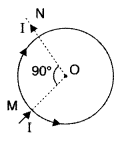
Obtain the net magnetic field at the centre of the loop.
(Comptt. Delhi 2011)
Answer:
(a) Biot-Savart Law to derive expression of
magnetic field.
According to Biot-Savart’s law, “magnetic field acting at a
particular point due to current carrying element is proportional to the division
of cross product of current element and position vector of point where the field
is to be calculated from the current element to the cube of the distance between
current element and the point where the field is to be calculated”.

Magnetic field on the axis of circular current loop :
As in a special case we may obtain the field at the centre of
the loop. Here x = 0, and we obtain![]()
In a current loop, both the opposite faces behave as opposite
poles, making it a magnetic dipole. One side of the current carrying coil
behaves like the N-pole and the other side as the S-pole of a magnet.
Magnetic field lines due to circular coil.
(a) Magnetic field lines :
(b) Moving coil galvanometer. It is a device used for the
detection and measurement of small electric current.
Principle. The working
is based on the fact that a current carrying coil suspended in a magnetic field
experiences a torque.
Construction. It consists of a coil having a large
number of turns of insulated copper wire wound on a metallic frame. The coil is
suspended by means of a phosphor-bronze strip and is surrounded by a horse-shoe
magnet NS. A hair spring is attached to lower end of the coil. The other end of
the spring is attached to the scale through a pointer.
Working. When current is passed, say along ABCD, the couple acts on it. Since the plane remains always parallel to the magnetic field in all positions of the coil (radial field), the force on the vertical arms always remains perpendicular to the place of the coil.
Let, I be the current flowing through coil,
B be magnetic field supposed
to be uniform and always parallel to the coil, A be area of the coil
Deflecting torque acting on the coil is,
τ = nI BA sin 900
Due to deflecting torque, the coil rotates and suspension wire gets twisted.
A restoring torque is set up in the suspension fibre. If <|) is angle through
which the coil rotates and k is the restoring torque per unit angular twist,
then restoring torque, τ = kϕ
In equilibrium,
Deflecting torque =
Restoring torque
This provide a linear scale for the galvanometer.
Function
of a radial magnetic field : Radial magnetic field being normal in all
directions is formed to get maximum torque.
Function of Soft iron core, which
not only makes the field radial but also increases the strength of the magnetic
field.
(c) One uses a shunt resistance in parallel with the galvanometer, so
that most of the current passes through the shunt. In the case of a voltmeter, a
resistance of large value is used in series because it must draw a very small
current, otherwise the voltage measurement will disturb the original set up by
an amount which is very large.
(b) Let current I be divided at
point M into two parts I1 and
I2; in bigger and smaller parts of the loop respectively. Magnetic
field of current (clockwise) at point O :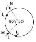
Magnetic field of current I2 (anticlockwise) at
point O :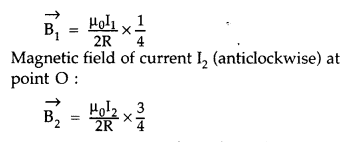
Net magnetic field,
\(\overrightarrow{\mathrm{B}}=\overrightarrow{\mathrm{B}_{1}}+\overrightarrow{\mathrm{B}_{2}}\)
But I1 = 3I2 (AS resistance of bigger part is three times
that of the smaller part of the loop)
Substituting I1 =
3I2 in equation (i), we get![]()
∴ Magnetic field at the centre of loop is zero.
Question 35.
(a) Show how Biot-Savart law can be alternatively expressed
in the form of Ampere’s circuital law. Use this law to obtain the expression for
the magnetic field inside a solenoid of length ‘l’, cross-sectional area ‘A’
having ‘N’ closely wound turns and carrying a steady current ‘I’.
Draw the
magnetic field lines of a finite solenoid carrying current I.
(b) A straight
horizontal conducting rod of length 0.45 m and mass 60 g is suspended by two
vertical wires at its ends. A current of 5.0 A is set up in the rod through the
wires.
Find the magnitude and direction of the magnetic field which should be
set up in (Comptt. Delhi 2011)
Answer:
(a) (i) Bio-Savart law and Ampere’s
Circuital law.
According to Biot-Savart’s law, “magnetic field acting at a
particular point due to current carrying element is proportional to the division
of cross product of current element and position vector of point where the field
is to be calculated from the current element to the cube of the distance between
current element and the point where the field is to be calculated”.

Magnetic field on the axis of circular current loop :
As in a special case we may obtain the field at the centre of
the loop. Here x = 0, and we obtain![]()
In a current loop, both the opposite faces behave as opposite
poles, making it a magnetic dipole. One side of the current carrying coil
behaves like the N-pole and the other side as the S-pole of a magnet.
(b) Biot-Savart law can be expressed as Ampere’s Circuital law by considering
the surface to be made up of a large number of loops. The sum of the tangential
components of the magnetic field multiplied by the length of all such elements
leads to integral. Ampere’s circuital law states that this’ integral is equal to
p0 times the total current passing through that surface, i.e.,![]()
(ii) Expression for magnetic field inside a solenoid. Let ‘n’ be the number
of turns per unit length. Then total number of turns in the length ‘h’ is
nh.
Hence, total enclosed current = nhl
Using Ampere’s circuital
law,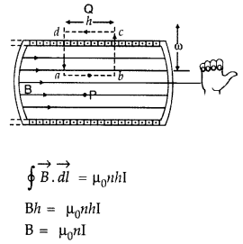
(iii) Magnetic field lines of a finite solenoid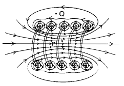
(b) As per the figure given, magnetic field must be
vertically inwards, to make tension zero.
Therefore, force on current
carrying conductor and the weight of conductor are equal and opposite; and
balance each other.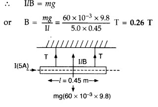
Direction : Perpendicular to the direction of
Question 36.
(a) State Ampere’s circuital law expressing it in the
integral form.
(b) Two long coaxial insulated solenoids S1 and
S2 of equal lengths are wound one over the other as shown in the
figure. A steady current ‘l’ flows through the inner solenoid S1 to the other
end B, which is connected to the outer solenoid S2 through which the same
current ‘l’ flows in the opposite direction so as to come out at end A. If
n1 and n2 are the numbers of turns per unit length, find
the magnitude and direction of the net magnetic field at a point
(i) inside
on the axis and
(ii) outside the combined system. (CBSE Delhi 2014)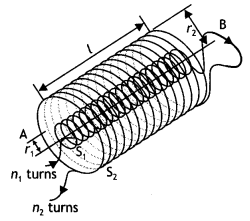
Answer:
(a) The line integral of B around any closed path equals
µol, where l is the total steady current passing through any surface
bounded by the closed path.” Mathematically
\(\oint \vec{B} \cdot
\overrightarrow{d L}=\mu_{0} I\)
(b) (i) The magnetic field due to a current-carrying solenoid:
B =
µon l
where n = number of turns per unit length
l = current through the
solenoid
Now, the magnetic field due to solenoid S1 will be in the upward
direction and the magnetic field due to S2 will be in the downward
direction (by right-hand screw rule).
In the upward direction
(ii) The magnetic field is zero outside a solenoid.
Question 37.
Three long straight parallel wires are kept as shown in the
Figure. The wire (3) carries a current l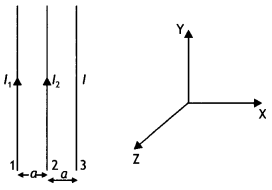
(i) The direction of flow of current l in wire (3) is such that the net force,
on a wire (1), due to the other two wires, is zero.
(ii) By reversing the
direction of l, the net force on the wire (2), due to the other two wires,
becomes zero. What will be the direction of current l, in the two cases? Also
obtain the relation between the magnitudes of currents l1,
l2, and l. (CBSE Delhi 2016C)
Answer:
Case 1: The direction of
flow of current in the wire (3) will be opposite to the direction of flow of
current in the wire (1), i.e. downwards.
Also \(\frac{\mu_{0} l_{1} l}{2
\pi(2 a)}=\frac{\mu_{0} l_{1} l_{2}}{2 \pi a}\)
or
l = 2l2
Case 2: The direction of flow of current in wire (3) will be same as the
direction of flow of current in wire (1), i.e. upwards. For zero force on wire
(2) we have
\(\frac{\mu_{0} l_{1} l_{2}}{2 \pi a}=\frac{\mu_{0} l l_{2}}{2
\pi a}\)
or
l = l1
Therefore l = l1 = 2
l2
Question 38.
Show mathematically that the cyclotron frequency does not
depend upon the speed of the particle.
Answer:
Due to the presence of the
perpendicular magnetic field the particle moves in a circle of radius r given
by
r = \(\frac{m v}{q B}\) ….(1)
The path of the particles in the dees is a semicircle and the time the
particle spends in each dees is length of the semi circular path velocity
t =
\(\frac{\text { length of the semi circular path }}{\text { velocity }}\)
=
\(\frac{\pi r}{v}=\frac{\pi m}{B q}\) …(2)
using equation (1)
The above time is independent of the radius of the path
and the velocity of the charged particle. Now the time period of the cyclotron
is twice the time spent by the particle in each dee. Thus
T = 2t = \(\frac{2 \pi m}{B q}\) …(3)
Hence cyclotron frequency or the magnetic resonance frequency is given by
v = \(\frac{1}{T}=\frac{B q}{2 \pi m}\) …(4)
which is independent of the speed of the particle.
Question 39.
State the principle of a cyclotron. Show that the time period
of revolution of particles in a cyclotron is independent of their speeds. Why is
this property necessary for the operation of a cyclotron? (CBSE Al 2016)
Answer:
Principle of cyclotron: It is based on the principle that the
positive ions can be accelerated to high energies with a comparatively smaller
alternating potential difference by making them cross the electric field again
and again, by making use of a strong magnetic field.
The necessary centripetal force required by charged particle to revolve in a
circular path in magnetic field is provided by force due to magnetic field,
i.e.
\(\frac{m v^{2}}{r}\) = Bqv
or
v = \(\frac{\text { Bqr }}{m}\)
So, the frequency of revolution is then given by
T = \(\frac{2 \pi r}{v}=2
\pi r \times \frac{m}{B q r}=\frac{2 \pi m}{B q}\)
It is clear from the expression that T is Independent of speed.
If this condition is not met the charged particle will very soon go out of step with the applied electricity and will not be accelerated.
Question 40.
(a) Write the expression for the magnetic force acting on a
charged particle moving with velocity v in the presence of magnetic field B.
Answer:
\(\vec{F}\) = q\((\vec{v} \times \vec{B})\)
(b) A neutron, an electron and an alpha particle moving with equal velocities
enter a uniform magnetic field going into the plane of the paper as shown. Trace
their paths in the field and justify your answer. (CBSE Delhi 2016)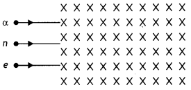
Answer:
The path area is shown.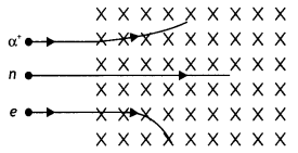
The radius of the circular path traveled by each particle is given by the
expression
r = \(\frac{m v}{B q}\) since B and v is the same therefore
we have r ∝ \(\frac{m}{q}\). Since neutron does not have a charge therefore it passes straight without deflection. The ratio m/q for an alpha particle is greater for an alpha particle therefore its path will be less curved.
Also by Fleming’s left-hand rule the alpha particle and the electron will experience a force in the direction as shown.
Question 41.
A long solenoid of length ‘L’ having N turns carries a
current l. Deduce the expression for the magnetic field in the interior of the
solenoid. (CBSE AI 2011C)
Answer:
Consider a rectangular path abed of
length L as shown in the figure below. Let us apply Ampere’s circuital law to
this rectangular path so that we have


But by Ampere’s circuital law we have
\(\oint \vec{B} \cdot \vec{d} L\) =
μ0Nl = μ0(nL)l …(2)
From equations (1) and (2) we have
BL = μ0nLl
or
B =
μ0 n l
But n = N/L, therefore we have
B = μ0 \(\frac{N l}{L}\)
This gives the value of a magnetic field inside a solenoid.
Question 42.
Using Biot-Savart’s law, derive an expression for the
magnetic field intensity at the center of a current-carrying circular coil.
Answer:
Consider a circular loop of radius r carrying a current l and having
a center at O as shown in the figure below.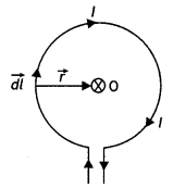
Consider a small current element dL on the loop. Then by Biot-Savart’s law the
magnitude of the magnetic field at the center of the loop due to the current
element we have
dB = \(\frac{\mu_{0}}{4 \pi} \frac{l d L \sin
\theta}{r^{2}}\) …(1)
In this case, the angle between the current element dL and the radius vector
is 90° therefore equation (1) can be written as
dB = \(\frac{\mu_{0}}{4 \pi}
\frac{l d L}{r^{2}}\) ….(2)
The circular loop can be considered to be consisting of such small elements
placed side by side, and then the magnetic intensities of these elements will be
in the same direction. Thus, the net intensity of B at the center of the loop is
given by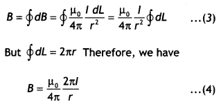
Question 43.
A charged particle q is moving in the presence of a magnetic
field B which is inclined to an angle 300 with the direction of the motion of
the particle. Draw the trajectory followed by the particle In the presence of
the field and explain how the particle describes this path. (CBSE Delhi
2019)
Answer:
Two components of velocity vector V are responsible for the
helical motion. Force on the charged particle due to the component normal to the
magnetic field acts perpendicular to the velocity and the magnetic field and
makes the particle follow a circular path. The component of velocity which is
along the magnetic field does not cause any force on the particle, hence the
particle continues to move in a straight line path due to this component so, the
resultant path will be helical.
The path is as shown.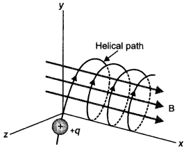
Question 44.
Two parallel coaxial circular costs of equal radius ‘R’ and an
equal number of turns ‘N’, carry equal currents ‘I’ in the same direction and
are separated by a distance ‘2R’. Find the magnitude and direction of the net
magnetic field produced at the mid-point of the line joining their centers.
Answer:
The magnetic field at a distance R from a circular coil is given by
the expression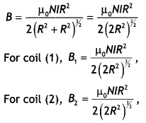
Both are directed in the same direction, therefore the resultant magnetic field
at the center is
B = \(\frac{\mu_{0} N l R^{2}}{\left(2 R^{2}\right)^{1 /
2}}\)
Question 45.
(a) State Biot-Savart’s law. Using this law, derive the
expression for the magnetic field due to a current-carrying circular loop of
radius ‘R’, at a point which is at a distance ‘x’ from Its center along the axis
of the loop.
Answer:
It states that for a small current element the small
magnetic field is given by the expression Biot-Savart’s law for a small current
element \(\overrightarrow{d B}=\frac{\mu_{0}}{4 \pi} \frac{I \overline{(d L}
\times \hat{r})}{r^{2}}\).
(b) Two small identical circular loops, marked (1) and (2), carrying equal
currents, are placed with the geometrical axes perpendicular to each other as
shown in the figure. Find the magnitude and direction of the net magnetic field
produced at point O.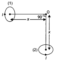
Answer:
The magnetic field at O due to the circular loop 1 is B1 =
\(\frac{\mu_{0} l R^{2}}{2\left(x^{2}+R^{2}\right)^{1 / 2}}\) directed towards
left.
The magnetic field at O due to the circular loop is B1 = \(\frac{\mu_{0} l R^{2}}{2\left(x^{2}+R^{2}\right)^{1 / 2}}\) directed upwards.
The net magnetic field is therefore
B =
\(\sqrt{B_{1}^{2}+B_{2}^{2}}=\sqrt{2} B_{1}=\frac{\mu_{0} l
R^{2}}{\sqrt{2}\left(x^{2}+R^{2}\right)^{3 / 2}}\)
The direction of the net magnetic field is 45° with the axis of the loop as
shown in the figure below.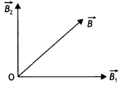
Question 46.
Derive an expression for the magnetic field along the axis of
an air-cored solenoid, using Ampere’s circuital law. Sketch the magnetic field
lines for a finite solenoid. Explain why the field at the exterior mid-point Is
weak while at the interior it is uniform and strong.
Answer:
A solenoid is
a coil of wire with a Length, which is Large as compared with its diameter.
Consider an ideaL soLenoid carrying current l and having n turns per unit
length.
(a) Consider a rectangular path abed of length L as shown in the
figure below. Let us apply Ampere’s circuital law to this rectangular path so
that we have


But by Ampere’s circuital law we have
\(\oint \vec{B} \cdot \vec{d} L\) =
μ0Nl = μ0(nL)l …(2)
From equations (1) and (2) we have
BL = μ0nLl
or
B =
μ0 n l
But n = N/L, therefore we have
B = μ0 \(\frac{N l}{L}\)
This gives the value of a magnetic field inside a solenoid.
(b) The sketch Is as shown below.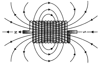
The magnetic field gets added inside the solenoid whereas it is not added
outside the solenoid.
Question 47.
(a)Using Ampere’s circuital law, obtain the expression for
the magnetic field due to a long solenoid at a point inside the solenoid on its
axis.
Answer:
Consider a rectangular path abed of length L as shown in the
figure below. Let us apply Ampere’s circuital law to this rectangular path so
that we have


But by Ampere’s circuital law we have
\(\oint \vec{B} \cdot \vec{d} L\) =
μ0Nl = μ0(nL)l …(2)
From equations (1) and (2) we have
BL = μ0nLl
or
B =
μ0 n l
But n = N/L, therefore we have
B = μ0 \(\frac{N l}{L}\)
This gives the value of a magnetic field inside a solenoid.
(b) In what respect is a toroid different from a solenoid? Draw and compare
the pattern of the magnetic field lines in the two cases.
Answer:
(b) In a
toroid magnetic field is uniform whereas in a solenoid it is different at the
two ends and the center.
The magnetic field lines around the two are as
shown.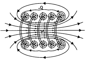
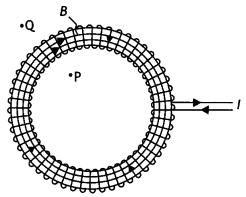
(c) How is the magnetic field inside a given solenoid made strong? (CBSE Al
2011)
Answer:
(i) By inserting a ferromagnetic substance inside the
solenoid.
(ii) By increasing the amount of current through the solenoid.
Question 48.
(a) Explain, giving reasons, the basic difference in
converting a galvanometer into
(i) a voltmeter
Answer:
A voltmeter is
always connected in parallel with the section of the circuit whose potential
difference has to be measured. Further, it must draw a small current, otherwise,
the voltage measurement will disturb the original setup by an amount that is
very large. Thus a large resistance is connected to the galvanometer in series
so as to minimize this effect.
(ii) an ammeter
Answer:
An ammeter measures current and is to be
connected in series in a circuit. A galvanometer has a large resistance,
therefore a shunt is connected to it in order to decrease its resistance such
that the current in the circuit is not altered.
(b) Two long straight parallel conductors carrying steady currents
l1 and l2 are separated by a distanced’. Explain briefly,
with the help of a suitable diagram, how the magnetic field due to one conductor
acts on the other. Hence deduce the expression for the force acting between the
two conductors. Mention the nature of this force. (CBSE At 2012)
Answer:
Consider two long, straight parallel wires separated by a distance ‘a’ and
carrying currents l1 and l2 in the same direction as
shown. We can easily determine the force on one wire due to the magnetic field
set-up by the other wire. Wire 2, which carries a current l2, sets up
a magnetic field B2 at the position of wire 1.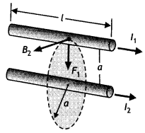
The direction of B2 is perpendicular to the wire, as shown in figure.
Now the magnetic force on length L of wire 1 is
\(\vec{F}_{1}=l_{1}\left(\vec{L} \times \vec{B}_{2}\right)\)
Since L is perpendicular to B2, the magnitude of F, is given by
F1 = l1 L B2 …(1)
But the field due to wire
2 is given by the relation
B2 = \(\frac{\mu_{0} l_{2}}{2 \pi a}\)
….(2)
Therefore, from equations 1 and 2 we have
F1= l1 L
B2 = l1 L\(\left(\frac{\mu_{0} l_{2}}{2 \pi
a}\right)=\frac{L \mu_{0} l_{1} l_{2}}{2 \pi a}\)
We can rewrite it in terms of force per unit length as
\(\frac{F_{1}}{L}=\frac{\mu_{0} l_{1} l_{2}}{2 \pi a}\) ….(3)
The direction of F1 is downward, towards wire 2, since \(\vec{L}
\times \vec{B}\) is downwards. If one considers the field set up at wire 2 due
to wire 1, the force F2 is found to be equal and opposite to
F1 which is in accordance with Newton’s third law of motion. When the
currents are in opposite directions, the forces are reversed and the wires repel
each other. Hence we find that the force per unit length of wire between two
parallel current-carrying wires is given by
F = \(\frac{\mu_{0} l_{1}
l_{2}}{2 \pi a}\)
Therefore, two conductors carrying current in the same direction attract each other whereas two conductors carrying current in the opposite directions repel each other.
The above expression can be used to define ampere, the SI unit of
current.
Let l1 = l2 = 1 ampere, a = 1 m then F = 2 ×
10-7 Nm-1
Thus we have
One ampere is that much current which when flowing through
each of the two infinitely long straight conductors held 1 meter apart in space,
produce a force of F = 2 × 10⁻⁷ N per meter of their length.
Question 49.
(a) State the underlying principle of a moving coil
galvanometer.
Answer:
A current-carrying coil placed in a magnetic field
experiences a torque.
(b) Give two reasons to explain why a galvanometer cannot as such be used to
measure the value of the current in a given circuit.
Answer:
- A galvanometer is a very sensitive device; it gives a full-scale deflection for a current of the order of a few pA.
- The resistance of the galvanometer is not very small, hence it will change the value of current in the circuit branch when connected in series in that branch.
(c) Define the terms:
(i) voltage sensitivity and
(ii) current
sensitivity of a galvanometer. (CBSE Delhi 2019)
Answer:
- Voltage sensitivity: Voltage sensitivity is defined as the deflection per unit potential difference applied.
- Current sensitivity: It is defined as the deflection per unit current.
Question 50.
(a) State Biot-Savart law. Deduce the expression for the
magnetic field due to a circular current carrying loop at a point lying on its
axis.
Answer:
It states that for a small current element the small
magnetic field is given by the expression Biot-Savart’s law for a small current
element \(\overrightarrow{d B}=\frac{\mu_{0}}{4 \pi} \frac{I \overline{(d L}
\times \hat{r})}{r^{2}}\).
(b) Two long parallel wires carry currents l1 and l1
flowing in the same direction. When a third current-carrying wire is placed
parallel and coplanar in between the two, find the condition when the third wire
would experience no force due to these two wires. (CBSE AI 2012C)
Answer:
Two current-carrying wires carrying current in the same direction attract and
those carrying current in the opposite direction repel. The current in the third
wire at the center should be opposite to the current in the two wires.
The conditions should be
- The center wire should carry current in the opposite direction to the two wires and
- The center wire should be closer to the wire carrying lesser current.
Question 51.
(a) Derive the expression for the torque on a rectangular
current-carrying loop suspended in a uniform magnetic field.
Answer:
The
figure below shows a rectangular loop of wire with length ‘a’ and breadth ‘b’. A
line perpendicular to the plane of the loop (i.e. a normal to the plane) makes
an angle Φ with the direction of the magnetic field B, and the loop carries a
current / as shown. Let the forces acting on the various sides of the loop be
\(\vec{F}_{1}\), \(\vec{F}_{2}\), \(\vec{F}_{3}\) and \(\vec{F}_{4}\) as
shown.
It follows from the expression for the force experienced by a conductor in a
magnetic field that force on arm AB is
\(\vec{F}_{1}=I(\overrightarrow{\mathrm{AB}} \times \vec{B})\) …(1)
(in the
plane of the paper and is directed upwards as shown).
The force on arm CD is given by \(\vec{F}_{2}=l(\overrightarrow{\mathrm{CD}}
\times \vec{B})\) …(2)
(in the plane of the paper and is directed downwards
as shown.)
Since these two forces are equal and opposite and have the same line of action therefore they cancel out each other’s effect and their resultant effect on the coil is zero.
Now the force on arm BC is
\(\vec{F}_{3}=l(\overrightarrow{\mathrm{BC}}
\times \vec{B})\) …(3)
(acts perpendicular to the plane of the paper and is
directed outwards as shown) Finally the force on arm DA is
\(\vec{F}_{4}=I(\overrightarrow{\mathrm{DA}} \times \vec{B})\) …(4)
(acts
perpendicular to the plane of the paper and is directed inwards as shown in
figure).
Both forces F<sub>3</sub> and F4 make an angle of 90° with the
direction of the magnetic field. Therefore, in magnitude, these forces are given
by
F3 = F4 = l a B sin90° = l a B …(5)
The lines of action of both these forces are perpendicular to the plane of
the paper. The two forces F3 and F4 lie along different
lines and each give rise to a torque about the X-axis. The two torques produce a
resultant torque in the + X direction. The arm of the couple (perpendicular
distance between the lines of action of the two forces) from the figure below is
given by
The arm of couple = b Sin Φ …(6)
Therefore, by the definition of torque we have
Torque = either force × arm
of couple Using equations (5) and (6) we have
Torque = l B a × b Sin Φ
But
a b = A, area of the coil, therefore τ = l B A Sin Φ
(b)
A proton and a deuteron having equal momenta enter in a region of the uniform
magnetic field at a right angle to the direction of the field. Depict their
trajectories in the field. (CBSE Delhi 2013)
Answer:
The radius of the
curved path which will be followed by the two particles is given by the
expression r = \(\frac{m v}{B q}\)
As md > mp it will follow the path of a bigger
radius.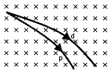
Question 52.
State Biot-Savart law, expressing it in the vector form. Use
it to obtain the expression for the magnetic field at an axial point, distance
‘d’ from the center of a circular coil of radius ‘a’ carrying current ‘l’. Also,
find the ratio of the magnitudes of the magnetic field of this coil at the
center and at an axial point for which d = a \(\sqrt{3}\) (CBSE Delhi 2013C)
Answer:
(a) It states that the magnetic field due to a current element dl at
a distance r from it is given by the expression
dB = \(\frac{\mu_{0}}{4 \pi} \frac{l d l \sin \theta}{r^{2}}\). In vector
form it is written as
\(\overrightarrow{d B}=k_{m} \frac{l mid
\overrightarrow{d L} \times \hat{r}}{r^{2}}\)
Consider a circular loop of wire of radius R located in the YZ plane and
carrying a steady current / as shown in the figure below. Let us calculate the
magnetic field at an axial point P a distance x from the center of the loop.
From the figure it is clear that any element dL is perpendicular to r,
furthermore, all the elements around the loop are at the same distance r from P,
where r2 = X2 + R2. Hence by Biot-Savart’s law,
the magnetic field at point P due to the current element dL is given by
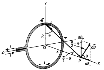
The direction of the magnetic field dB due to the eLement dL is perpendicular to
the plane formed by r and dL as shown in the figure above. The vector dB can be
resolved into components dB aLong the X-axis and dB which is perpendicular to
the X-axis. When the components perpendicular to the X-axis are assumed over the
whole loop, the result is zero. That is, by symmetry any element on one side of
the loop will set up a perpendicular component that cancels the component setup
by an element diametrically opposite it. Therefore, it is obvious that the
resultant magnetic field at P will be along the X-axis. This result can be
obtained by integrating the components dBx = dB cos θ.
Therefore,
we have
where the integral is to be taken over the entire loop since θ,x and R are
constants for all elements of the loop and since
cos θ =
\(\frac{R}{\sqrt{x^{2}+R^{2}}}\)
B = \(\frac{\mu_{0} l R}{4 \pi\left(x^{2}+R^{2}\right)^{3 / 2}} \oint d L=\frac{\mu_{0} l R^{2}}{2\left(x^{2}+R^{2}\right)^{1 / 2}}\)
To find the magnetic field at the centre of the loop setting x = O in equation the above equation we have B = \(\frac{\mu_{0} l}{2 R}\)
Now magnetic field at the centre of a circular coil is
\(B_{C}=\frac{\mu_{0} l}{2 a}\) …(1)
Also magnetic field on the axial line when
d = a\(\sqrt{3}\) is
From (1) and (2) we have
\(\frac{B_{C}}{B_{\text {axial }}}=\frac{\mu_{0}
l}{2 a} \times \frac{16 a}{\mu_{0} l}\) = 8
Question 53.
A straight wire carrying a current of 12 A is bent into a
semi-circular arc of radius 2.0 cm as shown in figure (a) Consider the magnetic
field B at the center of the arc
(a) What is the magnetic field due to the
straight segments?
(b) In what way the contribution to B from the semicircle
differs from that of a circular loop and in what way does it resemble?
(c)
Would your answer be different if the wire were bent into a semi-circular arc of
the same radius but in the opposite way as shown in figure (b)? (NCERT)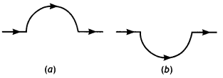
Answer:
(a) dl and r for each element of the straight segments are parallel.
Therefore \(d \vec{L} \times \hat{r}\) =0. Straight segments do not contribute
to the magnetic field at the center of the semicircular arc.
(b) For all segments of the semicircular arc \(d \vec{L} \times \hat{r}\) are
all parallel to, each other (into the plane of the paper). All such
contributions add up in magnitude. Hence the direction of B for a semicircular
arc is given by the right-hand rule and magnitude is half that of a circular
loop. Thus
B = \(\frac{1}{2} \frac{\mu_{0} l}{2 r}=\frac{4 \pi \times 10^{-7}
\times 12}{4 \times 2 \times 10^{-2}}\) = 9 × 10⁻⁴ T normal to the
plane of the paper going into it.
(c) Same magnitude of B but opposite in direction to that in (b)
Question 54.
A long straight wire carrying a current of 25 A rests on a
table as shown in the figure. Another wire PQ of length 1 m, mass 2.5 g carries
the same current but in the opposite direction. The wire PQ is free to slide up
and down. To what height will PQ rise? (NCERT Exemplar)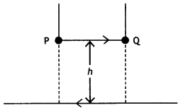
Answer:
Given l1 = l1 = 25 A, L = 1 m, m = 2.5 g = 2.5
× 10-3 kg
The repulsive force between PQ and the wire on the table
will balance the weight of wire PQ. Let this happen when PQ is at a height h
above the wire, then
F = mg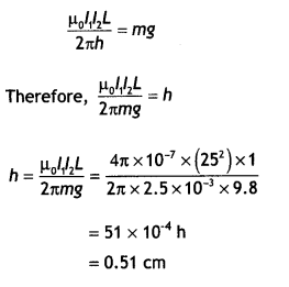
Question 55.
Two straight parallel conductors carry steady currents
l1 and l2 separated by a distance d. if currents are
flowing in the same direction, show how the magnetic field set-up in one
produces an attractive force on the other. Obtain the expression for force.
Hence define one ampere. (CBSE Delhi 2016)
Answer:
Consider two long,
straight parallel wires separated by a distance ‘a’ and carrying currents
l1 and l2 in the same direction as shown. We can easily
determine the force on one wire due to the magnetic field set-up by the other
wire. Wire 2, which carries a current l2, sets up a magnetic field
B2 at the position of wire 1.
The direction of B2 is perpendicular to the wire, as shown in figure.
Now the magnetic force on length L of wire 1 is
\(\vec{F}_{1}=l_{1}\left(\vec{L} \times \vec{B}_{2}\right)\)
Since L is perpendicular to B2, the magnitude of F, is given by
F1 = l1 L B2 …(1)
But the field due to wire
2 is given by the relation
B2 = \(\frac{\mu_{0} l_{2}}{2 \pi a}\)
….(2)
Therefore, from equations 1 and 2 we have
F1= l1 L
B2 = l1 L\(\left(\frac{\mu_{0} l_{2}}{2 \pi
a}\right)=\frac{L \mu_{0} l_{1} l_{2}}{2 \pi a}\)
We can rewrite it in terms of force per unit length as
\(\frac{F_{1}}{L}=\frac{\mu_{0} l_{1} l_{2}}{2 \pi a}\) ….(3)
The direction of F1 is downward, towards wire 2, since \(\vec{L}
\times \vec{B}\) is downwards. If one considers the field set up at wire 2 due
to wire 1, the force F2 is found to be equal and opposite to
F1 which is in accordance with Newton’s third law of motion. When the
currents are in opposite directions, the forces are reversed and the wires repel
each other. Hence we find that the force per unit length of wire between two
parallel current-carrying wires is given by
F = \(\frac{\mu_{0} l_{1}
l_{2}}{2 \pi a}\)
Therefore, two conductors carrying current in the same direction attract each other whereas two conductors carrying current in the opposite directions repel each other.
The above expression can be used to define ampere, the SI unit of
current.
Let l1 = l2 = 1 ampere, a = 1 m then F = 2 ×
10-7 Nm-1
Thus we have
One ampere is that much current which when flowing through
each of the two infinitely long straight conductors held 1 meter apart in space,
produce a force of F = 2 × 10⁻⁷ N per meter of their length.
Question 55 a.
(a) In a moving coil galvanometer, why is the magnetic field
required to be radial?
Answer:
The radial field is always normal to the
surface of the coil in all positions of the coil, i.e. θ = 0. The radial field
ensures a linear relation between 0 and l in a moving coil galvanometer.
(b) A 100 turn closely wound circular coil of radius 10 cm carries a current
of 3.2 A.
Calculate (i) the magnetic field at the centre of the coil, and
(ii) its magnetic moment. (CBSE2019C)
Answer:
Here N = 100, r = 10 cm =
0.1 m,
l = 3.2 A, B = ?, p = ?
(i) At the centre of the coil
(ii)Magnetic moment
p = NIA
= 100 × 3.2 × π × (0.1 )2 ≃ 10
Am2
Question 56.
State Ampere’s circuital law. Use this law to find a magnetic
field due to a straight infinite current-carrying wire. How are the magnetic
field lines different from the electrostatic field lines? (CBSE Al 2016)
Answer:
Statement: “The line integral of B around any closed path equals
μ0 l, where l is the total steady current passing through any surface
bounded by the closed path.”
Consider a long circular wire of radius ‘a’ carrying a steady current (dc)
that is uniformly distributed along the cross-section of the wire as shown in
the figure. Let us calculate the magnetic field in the regions r ≥ a and r <
a. In region 1 let us choose a circular path of radius r centered at the wire.
From symmetry, we find that B is perpendicular to dL at every point on the
circular path.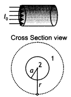
Since total current linked with the circular path is l0, therefore by
Ampere’s law we have
for r ≥ a
Magnetic field lines form closed loops while electrostatics
field lines do not.
Question 57.
(a) State Biot-Savart law in vector form.
Answer:
It
states that for a small current element the small magnetic field is given by the
expression Biot-Savart’s law for a small current element \(\overrightarrow{d
B}=\frac{\mu_{0}}{4 \pi} \frac{I \overline{(d L} \times \hat{r})}{r^{2}}\).
(b) Deduce the expression for the magnetic field at a point on the axis of a
current-carrying circular loop of radius ‘R’, distant V from the center, hence
write the magnetic field at the center of a loop. (CBSE AI 2015, Delhi
2018C)
Answer:
Consider a circular loop of wire of radius R located in the
YZ plane and carrying a steady current / as shown in the figure below. Let us
calculate the magnetic field at an axial point P a distance x from the center of
the loop. From the figure it is clear that any element dL is perpendicular to r,
furthermore, all the elements around the loop are at the same distance r from P,
where r2 = X2 + R2. Hence by Biot-Savart’s law,
the magnetic field at point P due to the current element dL is given by

The direction of the magnetic field dB due to the element dL is perpendicular to
the plane formed by r and dL as shown in the figure above. The vector dB can be
resolved into components dB along the X-axis and dB which is perpendicular to
the X-axis. When the components perpendicular to the X-axis are assumed over the
whole loop, the result is zero. That is, by symmetry any element on one side of
the loop will set up a perpendicular component that cancels the component setup
by an element diametrically opposite it. Therefore, it is obvious that the
resultant magnetic field at P will be along the X-axis. This result can be
obtained by integrating the components dBx = dB cos θ.
Therefore,
we have
where the integral is to be taken over the entire loop since θ,x and R are
constants for all elements of the loop and since
cos θ =
\(\frac{R}{\sqrt{x^{2}+R^{2}}}\)
B = \(\frac{\mu_{0} l R}{4 \pi\left(x^{2}+R^{2}\right)^{3 / 2}} \oint d L=\frac{\mu_{0} l R^{2}}{2\left(x^{2}+R^{2}\right)^{1 / 2}}\)
To find the magnetic field at the centre of the loop setting x = O in equation the above equation we have B = \(\frac{\mu_{0} l}{2 R}\)
Question 58.
Derive an expression for the maximum force experienced by a
straight conductor of length 1, carrying current I and kept in a uniform
magnetic field, B.
Answer:
Consider a straight segment of a conducting
wire; with length L and cross-section at area A, the current is from bottom to
top as shown In the figure below. The wire is in a uniform magnetic field B
perpendicular to the plane of the diagram and directed into the plane. Let us
assume that the moving charges are positive.
The drift velocity is upward, perpendicular to B. The average force
experienced by each charge is
\(\vec{f}=q\left(\vec{v}_{d} \times
\vec{B}\right)\) …..(1)
Directed to the left as shown in the figure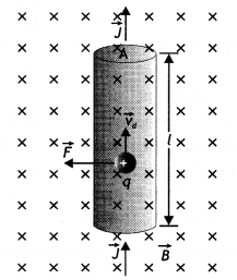
Since \(\vec{V}_{d}\) and \(\vec{B}\) are perpendicular, the magnitude of the
force is given by
f = q vd B …(2)
Let n be the number density of charges, i.e. number of charges per unit
volume. A segment of the conductor with length L has volume V = A L and contains
a number of charges N given by
N = n A L …(3)
Now the total force F on all the charges moving in this segment is
F = N f
= (n A L) q vd B = (n q vd A) (L B)
But n q vd A = l, therefore the above equation becomes
F = B l
L …(4)
Question 59.
Derive an expression for the torque on a rectangular coil of
area A, carrying a current l and placed in a magnetic field B, the angle between
the direction of 8 and the vector perpendicular to the plane of the coil is θ.
(CBSE Delhi 2019)
Answer:
The figure below shows a rectangular loop of
wire with length ‘a’ and breadth ‘b’. A line perpendicular to the plane of the
loop (i.e. a normal to the plane) makes an angle Φ with the direction of the
magnetic field B, and the loop carries a current / as shown. Let the forces
acting on the various sides of the loop be \(\vec{F}_{1}\), \(\vec{F}_{2}\),
\(\vec{F}_{3}\) and \(\vec{F}_{4}\) as shown.
It follows from the expression for the force experienced by a conductor in a
magnetic field that force on arm AB is
\(\vec{F}_{1}=I(\overrightarrow{\mathrm{AB}} \times \vec{B})\) …(1)
(in the
plane of the paper and is directed upwards as shown).
The force on arm CD is given by \(\vec{F}_{2}=l(\overrightarrow{\mathrm{CD}}
\times \vec{B})\) …(2)
(in the plane of the paper and is directed downwards
as shown.)
Since these two forces are equal and opposite and have the same line of action therefore they cancel out each other’s effect and their resultant effect on the coil is zero.
Now the force on arm BC is
\(\vec{F}_{3}=l(\overrightarrow{\mathrm{BC}}
\times \vec{B})\) …(3)
(acts perpendicular to the plane of the paper and is
directed outwards as shown) Finally the force on arm DA is
\(\vec{F}_{4}=I(\overrightarrow{\mathrm{DA}} \times \vec{B})\) …(4)
(acts
perpendicular to the plane of the paper and is directed inwards as shown in
figure).
Both forces F3 and F4 make an angle of 90° with the
direction of the magnetic field. Therefore, in magnitude, these forces are given
by
F3 = F4 = l a B sin90° = l a B …(5)
The lines of action of both these forces are perpendicular to the plane of
the paper. The two forces F3 and F4 lie along different
lines and each give rise to a torque about the X-axis. The two torques produce a
resultant torque in the + X direction. The arm of the couple (perpendicular
distance between the lines of action of the two forces) from the figure below is
given by
The arm of couple = b Sin Φ …(6)
Therefore, by the definition of torque we have
Torque = either force × arm
of couple Using equations (5) and (6) we have
Torque = l B a × b Sin Φ
But
a b = A, area of the coil, therefore τ = l B A Sin Φ
Question
60.
Draw a schematic sketch of a cyclotron. State its working principle and
write its two uses. (CBSE 2019C)
Answer:
Cyclotron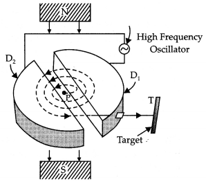
Working Principle: It is based on the principle that a positively charged
particle can acquire very large energy with the small alternating potential
difference if the particle is made to cross again and again the electric field
produced by alternating potential difference applied and a strong perpendicular
magnetic field is applied.
Uses:
(a) It is used to accelerate positively charged particles to very
high energies.
(b) Cyclotrons are a source of high-energy beams for nuclear
physics experiments.
Question 61.
(a) Draw a schematic sketch of a moving coil galvanometer and
describe briefly its working.
Answer:
Principle: It is based on the
principle that the positive ions can be accelerated to high energies with a
comparatively smaller alternating potential difference by making them cross the
electric field again and again, by making use of a strong magnetic
field.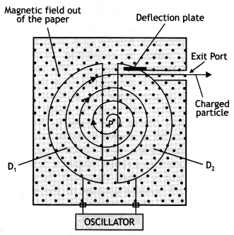
Construction: It consists of two D-shaped, hollow metal dees D1 and
D2. The dees are placed with a small gap in between them. The dees
are connected to a source of high frequency alternating potential difference.
The dees are evacuated in order to minimize energy losses resulting from
collisions between the ions and air molecules. The whole apparatus is placed
between the poles of an electromagnet as shown in the figure below. The magnetic
field is perpendicular to the plane of the dees.
Working: In a cyclotron, particles of mass m and charge q move inside an evacuated chamber in a uniform magnetic field B that is perpendicular to the plane of their paths. The alternating potential difference applied between the hollow electrodes D1 and D2 create an electric field in the gap between them which changes precisely twice in each revolution so that the particles get a push each time they cross the gap.
The pushes increase their speed and kinetic energy, boosting them into paths
of larger radius. The electric field increases the speed and the magnetic field
makes the particles move in circular paths. Due to the presence of the
perpendicular magnetic field the particle moves in a circle of radius r given
by
r = \(\frac{m v}{q B}\) …(1)
The path of the particles in the dees is a semicircle and the time the
particle spends in each dee is semi-circular
τ = \(\frac{\text { length of
the semi-circular path }}{\text { velocity }}=\frac{\pi r}{v}=\frac{\pi m}{B
q}\) by using equation (1)
The above time is independent of the radius of the path and the velocity of the charged particle. Hence the charged particle spends the same time in each dee and encounters a dee of opposite polarity whenever it comes into the gap between the dees and thus is continuously accelerated.
(b) “Increasing the current sensitivity of a galvanometer does not
necessarily increase the voltage sensitivity.” Justify’ this statement. (CBSE
Delhi 2014C)
Answer:
Voltage and current sensitivities are related as VS =
\(\frac{CS}{R}\) .
An increase in current sensitivity may lead to an increase in the resistance of the coil. Thus the factor CS/R may not be affected.
Question 62.
Explain with the help of a labeled diagram the underlying
principle, construction, and working of a moving coil galvanometer.
Answer:
It is an instrument used to detect weak currents in a circuit.
Principle: It is based on the principle that, whenever a loop carrying current is placed in a magnetic field, it experiences a torque, which tends to rotate it.
Construction: It consists of a rectangular or circular coil made by winding a fine insulated copper wire on an aluminum frame. A thin phosphor bronze strip from a torsion head, which is connected to a terminal screw, suspends this coil. The lower end of the coil is connected to a fine spring which is connected to another terminal screw. The coil hangs in space between the pole pieces of a powerful horseshoe magnet NS as shown in the figure below. The pole pieces are made concave cylindrical.
This provides a radial magnetic field. Since the field is radial, therefore
the plane of the coil remains parallel to the magnetic field in all the
orientations of the coil. In between the pole pieces, within the coil, lies a
soft iron cylindrical piece called ‘core’. The core does not touch the coil
anywhere. The whole arrangement is enclosed in a non-magnetic box to protect it
from air currents. Three leveling screws are provided at the base.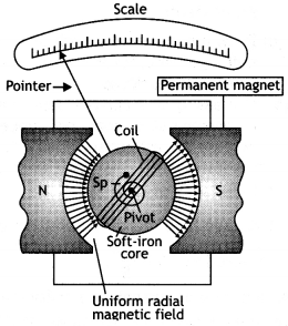
Question 63.
Explain with the help of a labeled diagram the underlying
principle, construction, and working of a cyclotron. (CBSE Delhi 2019)
Answer:
Principle: It is based on the principle that the positive ions can be
accelerated to high energies with a comparatively smaller alternating potential
difference by making them cross the electric field again and again, by making
use of a strong magnetic field.
Construction: It consists of two D-shaped, hollow metal dees D1 and
D2. The dees are placed with a small gap in between them. The dees
are connected to a source of high frequency alternating potential difference.
The dees are evacuated in order to minimize energy losses resulting from
collisions between the ions and air molecules. The whole apparatus is placed
between the poles of an electromagnet as shown in the figure below. The magnetic
field is perpendicular to the plane of the dees.
Working: In a cyclotron, particles of mass m and charge q move inside an
evacuated chamber in a uniform magnetic field B that is perpendicular to the
plane of their paths. The alternating potential difference applied between the
hollow electrodes D1 and D2 create an electric field in
the gap between them which changes precisely twice in each revolution so that
the particles get a push each time they cross the gap. The pushes increase their
speed and kinetic energy, boosting them into paths of larger radius. The
electric field increases the speed and the magnetic field makes the particles
move in circular paths. Due to the presence of the perpendicular magnetic field
the particle moves in a circle of radius r given by
r = \(\frac{m v}{q B}\)
…(1)
The path of the particles in the dees is a semicircle and the time the
particle spends in each dee is semi-circular
τ = \(\frac{\text { length of
the semi-circular path }}{\text { velocity }}=\frac{\pi r}{v}=\frac{\pi m}{B
q}\) by using equation (1)
The above time is independent of the radius of the path and the velocity of the charged particle. Hence the charged particle spends the same time in each dee and encounters a dee of opposite polarity whenever it comes into the gap between the dees and thus is continuously accelerated.
Question 64.
The figure below shows a long straight wire of circular
cross-section (radius a) carrying steady current l. The current is uniformly
distributed across this cross-section. Calculate the magnetic field in the
region r < a and r > a. Draw a graph showing the variation of a magnetic
field for the above two cases.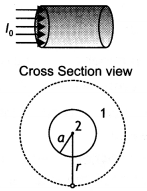
Answer:
Consider a long circular wire of radius ‘a’ carrying a steady current
(dc) that is uniformly distributed along the cross-section of the wire as shown
in the figure. Let us calculate the magnetic field in the regions r ≥ a and r
< a. In region 1 let us choose a circular path of radius r centered at the
wire. From symmetry, we find that B is perpendicular to dL at every point on the
circular path. Since total current linked with the circular path 1 is l0,
therefore by Ampere’s law we have
for r ≥ a
Now consider the interior of the wire, i.e. region 2 where r < a. In this,
the current l enclosed by the path is less than l<sub>0</sub>. Since
the current is assumed to be uniform over the area of the wire,
Therefore
Now applying Ampere’s circuital rule to region 2 we have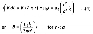
The magnetic field versus r for this system is as shown in the figure
below.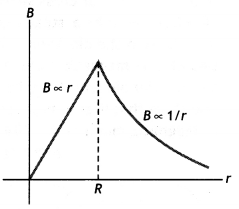
Question 64 a.
Draw the magnetic field lines due to a circular loop of area
\(\vec{A}\) carrying current I. Show that it acts as a bar magnet of magnetic
moment \(\vec{m}=I \vec{A}\). (CBSE Al 2015)
Answer:
The magnetic field
lines are as shown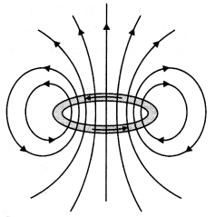
Magnetic field due to circular loop on its axis at far off points
B =
\(\frac{\mu_{0}}{4 \pi} \frac{2 I A}{X^{3}}\)
Magnetic field due to a bar magnet at its axial point is
B =
\(\frac{\mu_{0}}{4 \pi} \frac{2 m}{x^{3}}\)
Comparing the above two we have m = IA
Question 65.
(a) State Ampere’s circuital law. Use this law to obtain the
expression for the magnetic field inside an air-cored toroid of average radius
‘r, having ‘n’ turns per unit length and carrying a steady current.
(b) An
observer to the left of a solenoid of N turns each of cross-section area ‘A’
observes that a steady current I in it flows in the clockwise direction. Depict
the magnetic field lines due to the solenoid specifying its polarity and show
that it acts as a bar magnet of magnetic moment m = NIA. (CBSE Delhi
2015)
Answer:
(a) “The line integral of 8 around any closed path equal
μ0l, where l is the total steady current passing through any surface
bounded by the closed path.” Consider a toroidal solenoid. Let N be the number
of turns and l be the current passed through it. For a solenoid whose coils are
closely spaced, the field inside the solenoid is tangent to the dotted circular
path as shown in the figure and is the same at all points lying on the dotted
line.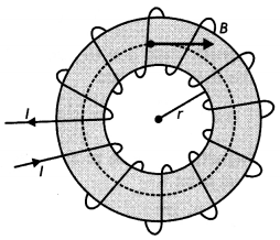
Therefore we have
\(\oint \vec{B} \cdot d \vec{L}\) = B ∮dL = B (2 π r)
…(1)
By Ampere’s circuital law we have ∮\(\overrightarrow{\mathbf{B}} \cdot d \vec{L}\) = μ0Nl …(2)
From equations 1 and 2 we have
B (2 π r) = μ0NI
or
B =
\(\frac{\mu_{0} N I}{2 \pi r}\) but
\(\frac{N}{2 \pi r}\) = n
i. e. number of turns per unit length Therefore we have B = μ0 n I
This gives the field inside a toroidal solenoid.
(b) The magnetic field lines and the polarity of the solenoid is as
shown.
Magnetic field due to the coil on its axis at far off points
B =
\(\frac{\mu_{0}}{4 \pi} \frac{2 N I A}{x^{3}}\)
Magnetic field due to a bar magnet at its axial point is
B =
\(\frac{\mu_{0}}{4 \pi} \frac{2 m}{x^{3}}\)
Comparing the above two we have m = NIA
Question 66.
(a) Use Biot-Savart law to derive the expression for the
magnetic field due to a circular coil of radius R having N turns at a point on
the axis at a distance ‘x’ from its center.
Draw the magnetic field lines due
to this coil.
(b) A current l enters a uniform loop of radius R at point M
and flows out at point N as shown in the figure. Obtain the net magnetic field
at the center of the loop. (CBSE Delhi 2015C)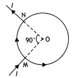
Answer:
(a) According to Biot-Savart law:
The magnitude of magnetic field
d \(\vec{B}\) , is due to a current element d \(\vec{l}\), is proportional to
current l and element length, dl.
inversely proportional to the square of the distance r.
Its direction is perpendicular to the plane containing d \(\vec{l}\) and \(\vec{r}\) .
In vector notation,
\(\overrightarrow{d B}=\frac{\mu_{0}}{4 \pi}, \frac{d
\vec{l} \times \vec{r}}{r^{3}}\)
Using Biot-Savart law, obtain the expression for the magnetic field due to a
circular coil of radius r, carrying a current I at a point on its axis distant x
from the centre of the coil. (CBSE Delhi 2018C)
Answer: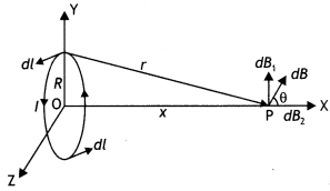
we have \(\overrightarrow{d B}=\frac{\mu_{0}}{4 \pi} I \frac{|d \vec{i} \times
\vec{r}|}{r^{3}}\)
r² = x² + R²
∴ dB = \(\frac{\mu_{0} I}{4 \pi} \frac{d l}{\left(X^{2}+R^{2}\right)^{3 / 2}}\)
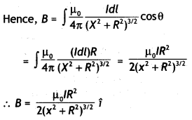
The magnetic fieLd Lines are as shown.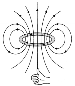
(b) At point O, the net magnetic field is the sum of fields due to two current
segments carrying currents /1 and l2. If the potential difference between points
A and B be V, then
V = I1 R1 =
I2R2
where R, is the resistance of segment subtending
an angle 90° at O and R2 is the resistance of segment subtending an
angle (360° – 90°) at O.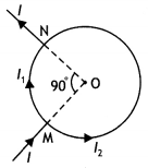
Now R1 = \(\frac{\pi / 2}{2 \pi} R=\frac{R}{4}\)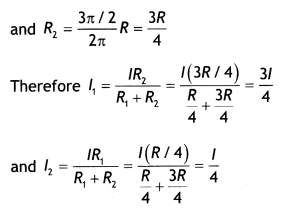
Now field B1, at O due to smaller segment is
directed inwards.
Now field B2 at 0 due to larger segment is
directed outwards
Hence net magnetic field in the center is
B1 – B2 =
\(\frac{3 \mu_{0} I}{32 r}-\frac{3 \mu_{0} I}{32 r}\) = 0
(ii) The velocity of the particle inside a cyclotron is given by v = \(\frac{B q r}{m}\) , which again depends upon the q/m ratio. The q/m ratio of an a particle is less than that of a proton, therefore a proton will come out with higher velocity.
Question 67.
(a) Define the SI unit of current in terms of the force
between two parallel current-carrying conductors.
(b) Two long straight
parallel conductors carrying steady currents la and lb
along the same direction are separated by a distance d. How does one explain the
force of attraction between them? If a third conductor carrying a current lc in
the opposite direction is placed just in the middle of these conductors, find
the resultant force acting on the third conductor. (CBSE Delhi 2018C)
Answer:
(a) The ampere is the value of that steady current which, when
maintained in each of the two very long, straight, parallel conductors of
negligible cross¬section, and placed one meter apart in vacuum, would produce on
each of these conductors a force equal to 2 × 10⁻⁷ newton per meter
of length.
(b) The wire (ii) experiences a force due to the magnetic field
caused by the current flowing in wire (i).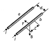
The magnetic field at any point on the wire (b) due to the current in the wire
(a) is perpendicular to the plane of two wires and pointing inwards and hence
force on it will be towards wire (a). Similarly, the force on the wire (a) will
be towards wire (b). Hence two wires carrying currents in the same direction
attract each other.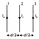
Force on wire (3) due to wire (1)
\(\frac{\mu_{0} l_{a} l_{c}}{2
\pi\left(\frac{d}{2}\right)}\) towards right
Force on wire 3 due to wire 2
\(\frac{\mu_{0} l_{b} l_{c}}{2
\pi\left(\frac{d}{2}\right)}\) towards Left
Net force on wire 3
\(\frac{\mu_{0} I_{c}}{\pi
d}\left[I_{a}-I_{b}\right]\) towards right nd °
Also accept
\(\frac{\mu_{0} I_{c}}{\pi d}\left[I_{b}-I_{a}\right]\)
towards left
Question 68.
(a) State Biot-Savart law and express it in the vector
form.
Answer:
(a) According to Biot-Savart law:
The magnitude of
magnetic field d \(\vec{B}\) , is due to a current element d \(\vec{l}\), is
proportional to current l and element length, dl.
inversely proportional to the square of the distance r.
Its direction is perpendicular to the plane containing d \(\vec{l}\) and \(\vec{r}\) .
In vector notation,
\(\overrightarrow{d B}=\frac{\mu_{0}}{4 \pi}, \frac{d
\vec{l} \times \vec{r}}{r^{3}}\)
(b) Using Biot-Savart law, obtain the expression for the magnetic field due
to a circular coil of radius r, carrying a current I at a point on its axis
distant x from the centre of the coil. (CBSE Delhi 2018C)
Answer:
we have \(\overrightarrow{d B}=\frac{\mu_{0}}{4 \pi} I \frac{|d \vec{i} \times
\vec{r}|}{r^{3}}\)
r² = x² + R²
∴ dB = \(\frac{\mu_{0} I}{4 \pi} \frac{d l}{\left(X^{2}+R^{2}\right)^{3 / 2}}\)

Question 69.
Derive an expression for the velocity y0 of a positive ion
passing undeflected through a region where crossed uniform electric field E and
magnetic field B are simultaneously present. Draw and justify the trajectory of
identical positive ions whose velocity has a magnitude less than
\(\left|v_{c}\right|\).
OR
A particle of mass m and charge q is in motion
at speed Y parallel to a long straight conductor carrying current I as shown
below.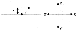
Find the magnitude and direction of the electric field required so that the
particle goes undefeated. (CBSE Sample Paper 2018-19)
Answer: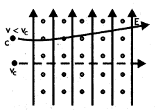
If the ion passes undeflected, therefore the magnetic and electric forces acting
on the ion must be equal and opposite.
Therefore
qE = Bqvc
vc = \(\frac{E}{B}\)
The trajectory would be as shown. Justification: For positive ions with speed v < vc. Force due to electric field wilt remains the same as It does not depend upon Vc.
But force due to the magnetic field will become Less than the initial value.
This unbalances the two, electric and magnetic, forces hence, the ion will
experience a net electric force. This will accelerate the ion along the
direction of the electric field. Since initiaL velocity is perpendicular to E,
the trajectory would be parabolic.
OR
For the charged particle to move
undeflected
Electric force = magnetic force
qE = Bq v
or
E=Bv
Now magnetic field at a distance r from the long straight conductor is
B =
\(\frac{\mu_{0} I}{2 \pi r}\)
This magnetic force Will act towards the wire.
Hence electric field is
E = \(\frac{\mu_{0} l v}{2 \pi r}\)
This electric field should act away from the wire.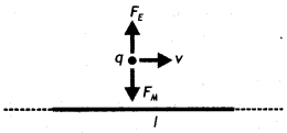
Numerical Problems:
Formulae for solving numerical problems
- Magnetic field due to a small current element dB = \(\frac{\mu_{0}}{4 \pi} \frac{l mid d L \sin \theta}{r^{2}}\)
- Magnetic field due to an infinitely long straight conductor B = \(\frac{\mu_{0}}{4 \pi} \frac{2l}{a}\)
- Magnetic field at the centre of a circular coil B = \(\frac{\mu_{0}}{4 \pi} \frac{2 \pi l}{r}\)
- Force on a charge moving in a magnetic field F = Bq v Sin θ
- The magnetic field inside a solenoid B = µ0 n I
- Force on a current-carrying conductor placed in a magnetic field F = BIL Sin θ
- Force between two current carrying conductors \(\frac{F_{1}}{L}=\frac{\mu_{0} l_{1} l_{2}}{2 \pi a}\)
- Torque on a current loop τ = BI n A sin θ
- Current in a galvanometer l = \(\frac{C}{n B A}\) sin θ
- Shunt required S = \(\frac{l_{8} G}{l-I_{g}}\)
- Resistance required R = \(\frac{v}{l_{g}}\) – G
- Radius of a charged particle in a magnetic field r = \(\frac{m v}{B q}=\frac{\sqrt{2 m E}}{B q}\)
Question 1.
A proton and an alpha particle having the same kinetic energy
are in turn allowed to pass through a uniform magnetic field perpendicular to
their direction of motion. Compare the radii of the paths of the proton and the
alpha particle.
Answer:
Given Eα = Ep, mα
= 4 mp, qα = 2qp, B is same for both. Now the radius of
the path followed is given by the expression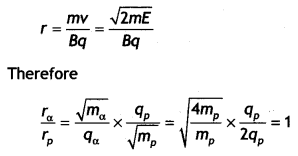
Question 2.
A circular coil of 30 turns and radius 8.0 cm carrying a current
of 6.0 A is suspended vertically in a uniform horizontal magnetic field of
magnitude 1.0 T. The field lines make an angle of 60° with the normal to the
coil. Calculate the magnitude of the counter-torque that must be applied to
prevent the coil from turning.
Answer:
Given n = 30, r = 8.0 cm = 8 ×
10-2 m,
l = 6.0 A, B = 1.0 T, θ = 60°, τ = ?
Using the formula
for torque
τ = BlnA
we have τ = Blnπr² sin θ
τ = 1 × 6 × 30 × 3.14 × (8 ×
10-2)2 × sin 60°
= 3.1 N m
Question 3.
How can a moving coil galvanometer be converted into an
ammeter? To increase the current sensitivity of a moving coil galvanometer by
50%, its resistance is increased so that the new resistance becomes twice its
initial resistance. By what factor does its voltage sensitivity change?
Answer:
Voltage sensitivity
= \(\frac{\alpha}{V}=\frac{\alpha}{I
R}=\frac{\text { current sensitivity }}{R}\)
When the current sensitivity increases by 50 % resistance becomes 2R.
New voltage sensitivity
= \(\frac{1+0.5}{2}\) = 0.75
Hence the voltage sensitivity decreases and becomes 75% of its original value.
Question 4.
A long straight conductor PQ carrying a current of 75 A is
fixed horizontally. Another long conductor XY is kept parallel to PQ at a
distance of 5 mm, in air. Conductor XY is free to move and carries a current l.
Calculate the magnitude and direction of current l for which the magnetic
repulsion just balances the weight of conductor XY (Mass per unit length for
conductor XY is 10-2 kg m-1.)
Answer:
Given l1 = 75 A, r = 5 mm = 5 × 10⁻³ m,
l2 = ? mass per unit length = 10-2kg m-1.
The force between the two wires should be repulsive and should balance the weight of the wire XY. Thus the current in wire XY will be opposite to that in wire PQ.
The force between the two current-carrying conductors is given by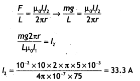
Question 5.
A galvanometer has a resistance of 30 Ω. It gives full-scale
deflection with a current of 2 mA. Calculate the value of the resistance needed
to convert it into an ammeter of range 0-0.3 A.
Answer:
Given G = 30 Ω, lg
= 2 mA= 2 × 10⁻³ A, S = ?, I = 0.3 A
Using the formula S =
\(\frac{I_{g} G}{I-I_{g}}\)
we have
S = \(\frac{I_{g} G}{I-I_{g}}\) = \(\frac{30 \times 2 \times
10^{-3}}{0.3-2 \times 10^{-3}}\) = 0.20 Ω
Question 6.
An infinitely long straight current-carrying wire produces a
magnetic field 8, at a point distant ‘a’ from it. What must be the radius of a
circular loop, so that, for the same current through it, the magnetic field at
(i) its center equals B/2 and (ii) an axial point, distant equal to the radius
of the loop, equals B?
Answer:
The magnetic field at a distance ‘a’ from
an infinitely long straight conductor is
B = \(\frac{\mu_{0} I}{2 \pi
a}\)
(i) Given Bc = B/2. Let r be the radius of the circular coil for which the magnetic field is B/2.
Magnetic field at the centre of a circular coil is \(B=\frac{\mu_{0} I}{2 \pi
a}\) Therefore
\(\frac{\mu_{0} l}{2 r}=\frac{1}{2} \times \frac{\mu_{0} l}{2
\pi a}\) or r = 2 π a
(ii) Magnetic field at the axial line of a loop is
B = \(\frac{\mu_{0} l
R^{2}}{2\left(x^{2}+R^{2}\right)^{1 / 2}}\)
Here x = R radius of the loop.
Therefore \(\frac{\mu_{0} I}{2 \pi
a}=\frac{\mu_{0} I R^{2}}{2\left(R^{2}+R^{2}\right)^{3 / 2}}\)
solving for R we have R = \(\frac{\pi a}{\sqrt{8}}\)
Question 7.
Calculate the value of resistance needed to convert a
galvanometer of resistance 120 ft, which gives a full-scale deflection for a
current of 5 mA, into a voltmeter of 0 – 50 V range.
Answer:
Given G = 120
Ω, lg = 5 × 10⁻³A, V= 50 V, R =?
Using the relation R = \(\frac{v}{l_{g}}\) – G we have
R = \(\frac{50}{5
\times 10^{-3}}\) -120 = 9880 Ω
Question 8.
Two infinitely long straight wires A1 and
A2 carrying currents l1 and l2 flowing in
the same directions are kept distance apart. Where should a third straight wire
A3 carrying current 1.5 l be placed between A1 and
A2 so that it experiences no net force due to A1 and
A2? Does the net force act on A3 depend on the current flowing
through it? (CBSE Delhi 2019)
Answer:
The diagram is as shown.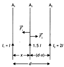
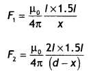
If no force is experienced by the conductor A3, then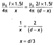
The net force on A3 does not depend upon the current flowing through
it.
Question 9.
An ammeter of resistance 0.80 Ω can measure current up to 1.0
A.
(a) What must be the value of shunt resistance to enable the ammeter to
measure current up to 5.0 A?
Answer:
Given G = 0.80 Ω, /g = 1.0 A, l = 5.0
A, S = ?, R<sub>A</sub> = ?
(a) Using the expression
S =
\(\frac{I_{g} G}{I-I_{0}}=\frac{1 \times 0.8}{5-1}=\frac{0.8}{4}\) = 0.2 Ω
(b) What is the combined resistance of the ammeter and the shunt? (CBSE Delhi
2013)
Answer:
Now RA = \(\frac{G S}{G+S}=\frac{0.8 \times
0.2}{0.8+0.2}\) = 0.016 Ω
Question 10.
A wire AB is carrying a steady current of 12 A and is lying
on the table. Another wire CD carrying 5A is held directly above AB at a height
of 1 mm. Find the mass per unit length of the wire CD so that it remains
suspended at its position when left free. Give the direction of the current
flowing in CD with respect to that in AB. (Take the value of g = 10 m
s-2) (CBSE AI 2013)
Answer:
Given l1 = 12 A, r = 1
mm = 1 × 10⁻³ m, l2 = 5 A, mass per unit length = ?
The force between the two wires should be repulsive and should balance the weight of the wire CD. Thus the current in wire CD will be opposite to that in wire AB.
The force between the two current¬carrying conductors is given by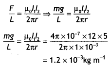
Question 11.
A square loop of side 20 cm carrying a current of I A is kept
near an infinitely long straight wire carrying a current of 2 A in the same
plane as shown in the figure.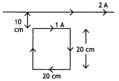
Calculate the magnitude and direction of the net force exerted on the loop due
to the current carrying conductor. (CBSEAI 2015C)
Answer:
Here, PQ = 20 cm
= 20 × 10-2 m,
PS = 20 cm = 10 × 10-2 m
Distance of PQ from AB,
r1 = 10 cm = 10 × 10-2 m
Distance of RS from AB,
r2 = (10 + 20) = 30 cm = 30 ×
10-2 m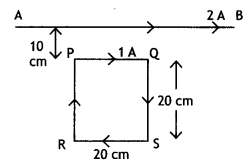
Current through long wire AB, l1 = 2 A
Current through rectangular
loop, l2 = 1 A
Force on the arm PQ,
F1 = \(\frac{\mu_{0} I_{1} I_{2}}{2 \pi a}\) × length PQ
F2 = \(\frac{2 \times 10^{-7} \times 2 \times 1 \times 20 \times
10^{-2}}{10 \times 10^{-2}}\) = 8 × 10⁻⁷ N
= 8 × 10⁻⁷ N
(towards AB)
Force on the arm RS,
F1 = \(\frac{\mu_{0} I_{1} I_{2}}{2 \pi
a}\) × length RS
F2 = \(\frac{2 \times 10^{-7} \times 2 \times 1 \times 20 \times 10^{-2}}{30 \times 10^{-2}}\) =2.66 × 10-7
= 2.66 × 10⁻⁷ N (away from AB)
Effective force on the Loop,
F= F1 – F2
=8 ×
10-7 – 2.66 × 10-7
= 5.34 × 10⁻⁷ N (towards
AB)
Question 12.
A square-shaped plane coil of area 100 cm2 of 200 turns
carries a steady current of 5A. It is placed in a uniform magnetic field of 0.2
T acting perpendicular to the plane of the coil. Calculate the torque on the
coil when its plane makes an angle. of 60° with the direction of the field. In
which orientation will the coil be in stable equilibrium? (CBSE Al 2015C)
Answer:
Given A= 10-2 m², n = 200, l = 5 A, θ = 60°, B = 0.2 T, τ =
?
Using the expression τ = B I n A sin θ we have
τ = 0.2 × 5 × 200 ×
10-2 × sin 60° = 20 Nm
Stable equilibrium, when the magnetic field
is in the direction of the coil.
Question 13.
A straight wire of mass 200 g and length 1.5 m carries a
current of 2 A. It is suspended in mid-air by a uniform horizontal magnetic
field B (figure). What is the magnitude of the magnetic field? (NCERT)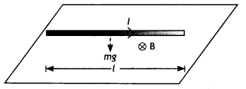
Answer:
For the wire to be suspended in mid-air, it must experience an upward
force F of magnitude F = B I L to balance its weight W= mg
Therefore, BI L =
mg
B = \(\frac{m g}{1 L}=\frac{0.2 \times 9.8}{2 \times 1.5}\) = 0.65 T
Question 14.
A cyclotron’s oscillator frequency is 10 MHz. What should be
the operating magnetic field for accelerating proto is? If the radius of its
dees is 60 cm what is the kinetic energy (in m MeV) of the proton beam produced
by the accelerator (e =1.60 × 10⁻¹⁹ C, mp = 1.67 × 10⁻²⁷
kg, 1 MeV = 1.6 × 10⁻¹³ J) (NCERT)
Answer:
The oscillator
frequency should be the same as the proton’s cyclotron frequency, i.e. 10 MHz =
107 Hz.
Therefore
B = \(\frac{2 \pi m v}{q}\)
= \(\frac{2 \times 3.14 \times 1.67 \times 10^{-27} \times 10^{7}}{1.6 \times 10^{-19}}\) = 0.66 T
Final velocity of protons is
V = r × 2πv = 0.6 × 6.3 × 107 =
3.78 × 10⁷ m s-1.
E = 1/2mv² = 1.67 × 10-27 × 14.3 × 1014 / (2 × 1.6 × 10-13) = 7 MeV
Question 15.
A solenoid of length 0.5 m has a radius of 1 cm and is made
up of 500 turns. Does it carry a current of 5 A. What is the magnitude of the
magnetic field inside the solenoid? (NCERT)
Answer:
Given n = 500/0.5 =
1000 turns per unit length. l = 5 A
The length L = 0.5 m and radius r = 0.01
m. Thus, L/a = 50,
Hence we have
B = μonl = 4π x
10-7 × 1000 × 5 = 6.28 × 10⁻³ T
Question 16.
A circular coil of wire consisting of 100 turns, each of a
radius 8.0 cm, carries a current of 0.40 A. What is the magnitude of the
magnetic field B at the center of the coil? (NCERT)
Answer:
Given n = 100,
r = 8.0 cm = 8.0 × 10⁻² m,
l = 0.40 A,B = ?
Using the expression B = \(\frac{\mu_{0} n l}{2 r}\)
we have
B =
\(\frac{\mu_{0} n l}{2 r}=\frac{4 \pi \times 10^{-7} \times 100 \times 0.40}{2
\times 8.0 \times 10^{-2}}\)
Question 17.
A horizontal overhead power line carries a current of 90 Ain
the east to west direction. What is the magnitude and direction of the magnetic
field due to the current 1.5 m below the line? (NCERT)
Answer:
Given l =
90 A, r = 1.5 m, B = ?
Using the expression B = \(\frac{\mu_{0} l}{2 \pi r}\)
we have
B = \(\frac{\mu_{0} l}{2 \pi r}=\frac{4 \pi \times 10^{-7} \times 90}{2
\times \pi \times 1.5}\) = 1.2 × 10⁻⁵ T
The magnetic field will be
towards the south.
Question 18.
A square coil of side 10 cm consists of 20 turns and carries
a current of 12 A The coil is suspended vertically and the normal to the plane
of the coil makes an angle of 30° with the direction of a uniform horizontal
magnetic field of magnitude 0.80 T. What is the magnitude of torque experienced
by the coil? (NCERT)
Answer:
Given L= 10 cm=0.1 m, A = (0.1)² = 0.01 m², n
= 20 , l = 12 A, θ = 30°, B = 0.80T, τ = ?
Using the expression τ = B l n A sin θ we have
τ = 0.80 × 12 × 20 × 0.01 ×
sin 30° = 0.96 Nm
Question 19.
A straight horizontal conducting rod of length 0.45 m and
mass 60 g is suspended by two vertical wires at its ends. A current of 5.0 A is
set up in the rod through the wires.
(i) What magnetic field should be set up
normally to the conductor in order that the tension in the wires is zero?
(ii) What will be the total tension in the wires if the direction of the current
is reversed keeping the magnetic field the same as before? (Ignore the mass of
the wires.) g = 9.8 ms-2 (NCERT)
Answer:
Given L = 0.45 m, m =
60 g, I = 5.0 A, B = ?
(i) The tension in the wires will be zero if the
weight of the rod is balanced by the force on it due to the magnetic field.
Therefore we have
B I L = mg
B = \(\frac{m g}{I L}=\frac{0.06 \times
9.8}{5.0 \times 0.45}\) = 0.26 T
Thus a horizontal magnetic field of magnitude 0.26 T normal to the conductor should be applied in such a direction that Fleming’s left-hand rule gives a magnetic force in the upward direction.
(ii) The tension will become twice the weight of the wire i.e.,
T = B / L
+ mg = mg + mg = 2 mg
Or
T= 2 × 0.06 × 9.8 = 1.176 N
Question 20.
A galvanometer coil has a resistance of 12 ohms and the meter
shows full-scale deflection for a current of 3 mA. How will you convert the
meter into a voltmeter of range 0 to 18 V? (NCERT)(CBSE 2019C)
V= 18 V, R =
?
We will connect a resistance R = \(\left(\frac{V}{l_{g}}-G\right)\) in
series with the galvanometer.
Therefore R = \(\frac{18}{3 \times 10^{-3}}\) – 12 = 5988 Ω
Question 21.
A galvanometer coil has a resistance of 15 ohms and the meter
shows full-scale deflection for a current of 4 mA. How will you convert the
meter into an ammeter of range 0 to 6A? (NCERT)
Answer:
Given G = 15 Ω,
lg = 4 mA = 4 × 10⁻³ A, l = 6 A, S = ?
We will connect a resistance S = \(\frac{l_{s} G}{l-l_{s}}\) in parallel with
the galvanometer.
Therefore S = \(\frac{4 \times 10^{-3} \times 15}{6-\left(4
\times 10^{-3}\right)}\) = 0.01 Ω
Or
S = 10 mΩ